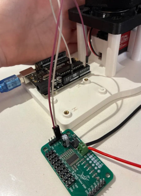
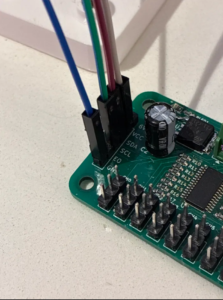
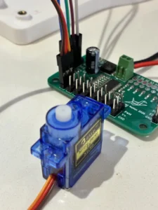
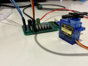

Step 2: Measure Servo Power at a Servo Port
Use any servo channel (CH7 is fine).
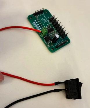
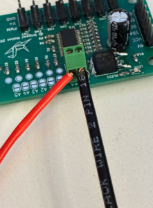
Place your black probe on the GND pin. Place your red probe on the V+ pin. Do not touch the PWM pin.
 You should see:
About 5.5–6 volts. This value should be very close to the value your power supply displays.
 If you read ~0V:
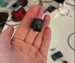
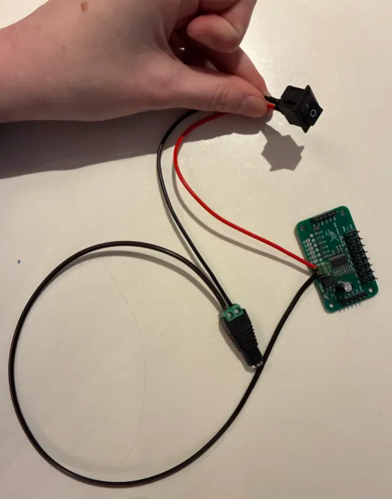
This means servo power is NOT reaching the board. First check if your power button is on. If not, turn it on.
 If you see 5.5-6V, but the voltage jumps or flickers, this means:
A weak or cracked solder joint
Power is barely making contact
What this tells us:
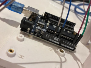
Arduino power works
Servo power path is broken
Check these parts:
Main green power terminal connector pins
Power input header
Large capacitors
 Fix:
Reheat every pin of the main power connector and power header.
Fix:
Reheat every pin of the main power connector and power header.
 Do NOT continue until you measure ~6V at the servo port.
If you read ~6V
Perfect. The servo power is confirmed. Now we check signal delivery.
Step 5: 30-Second Full Board Scan
This fixes most remaining issues.
Look for:
Solder bridges
Dull gray joints
Crooked parts
Pads soldered on only one side
If it looks suspicious:
...Reheat it!
Your motors should be spinning now.
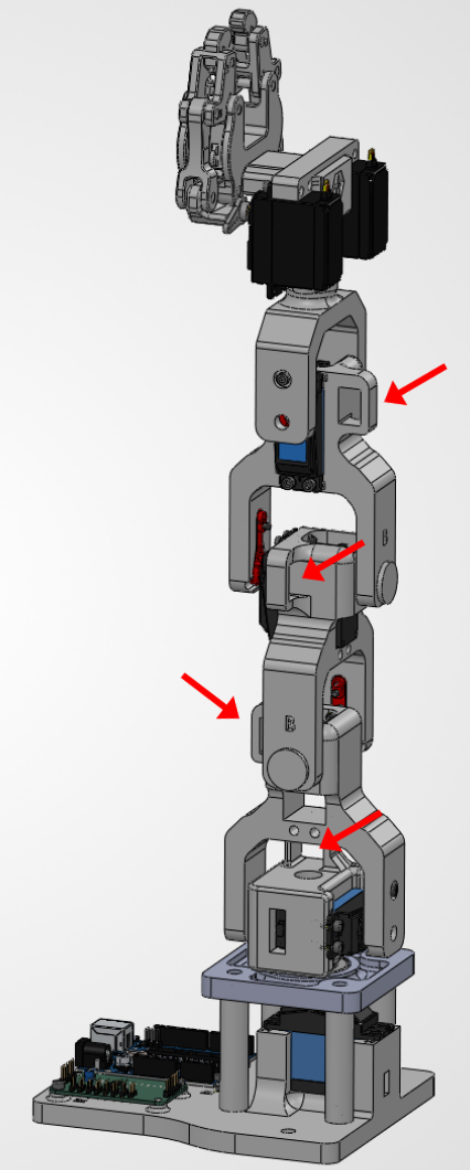
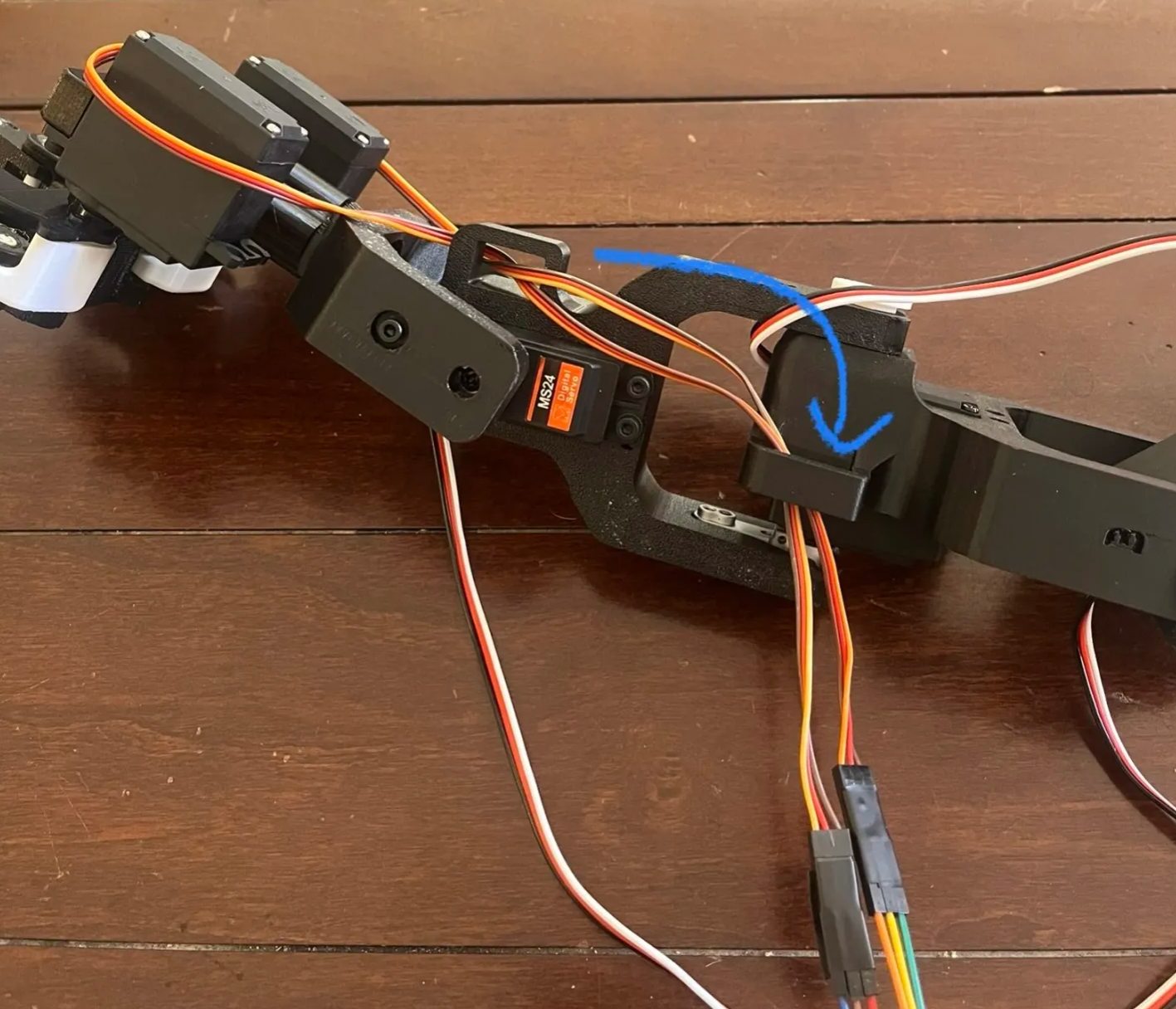
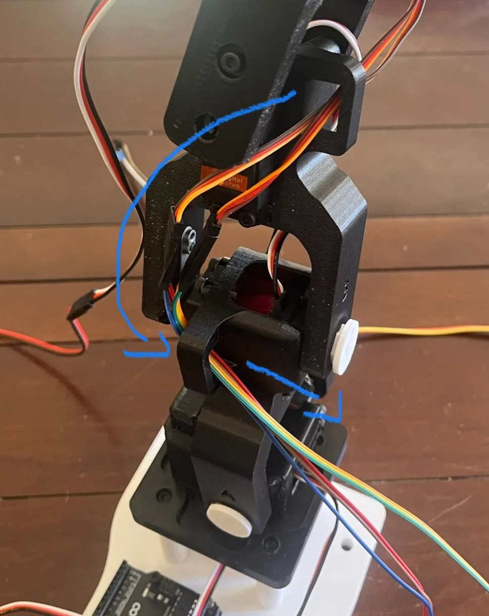
Wire Passthrough Channels
Here are some reasons why wire channels are important, as well as thoughts you should have as an engineer.
-
Protect wires from sharp edges, heat, and moving parts
-
Control routing so wires don’t interfere with mechanisms
-
Reduce strain & fatigue to improve reliability
-
Simplify assembly with predictable wire paths
-
Improve serviceability for repairs and upgrades
-
Clean, professional design that looks engineered
╰┈➤ Go to Step 2: Gather the Provided Wires
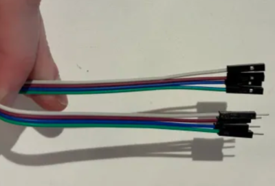
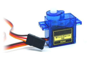
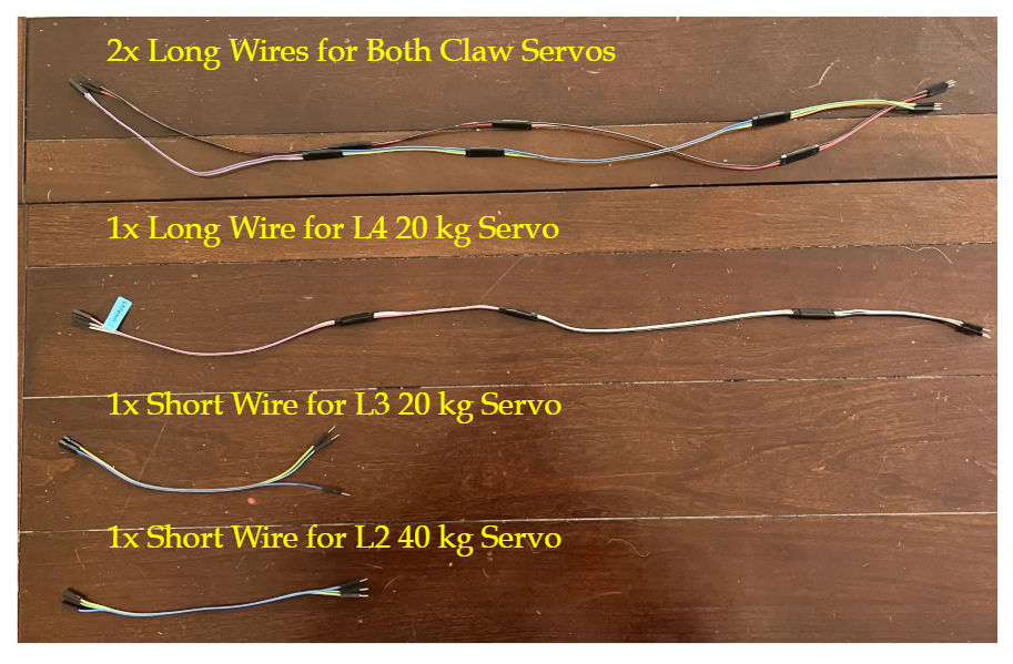
Gather the provided wires.
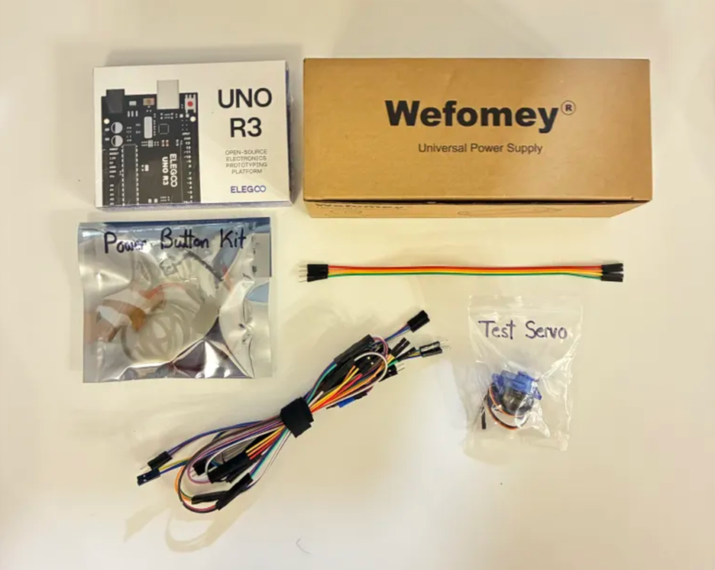
We have provided additional wires for you to attach to extend the servos' factory wire lengths. There are no additional wires needed for the T1 or L1 Servos, since their default wires are already long enough. These are all Male-Female wires because the holes they plug into are female (Servo) and male (header pins on the PCB). In electronics there are M-M, M-F, and F-F wires.
╰┈➤ Go to Step 3: Label the Wires
Label the wires.
Color doesn't matter too much, but a good rule of thumb is brown/black/green for ground. Servos all follow the same wiring scheme regardless of form factor or size.
For example, power line is always in the center. Take all sets of the extra wires and label the ground wire and the associated servo. You will thank yourself later. You can write on a piece of tape and loop it onto the FEMALE Side of the wires. If you know which servo it's for, and where ground is, you can easily attach the wires to the correct places every time. Example: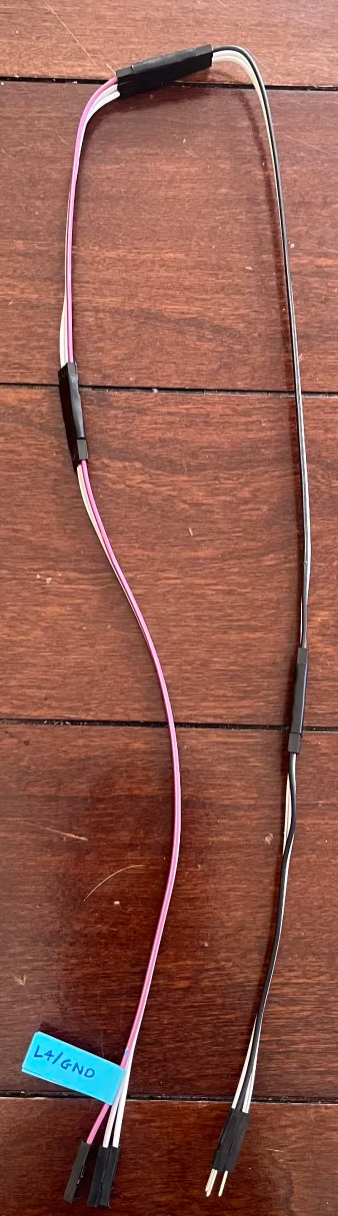 For the claws specifically, name them however you'd like (recommended: LC/RC), just be consistent with labeling in both the real world, and in code. You can label as much as you want. Don't just rely on your memory for what something is, it never hurts to be organized. As a great poet of our time once said...

╰┈➤ Go to Step 4: Connect the Wires and Start Looping!
Connect extension jumpers to their associated servo.
For every servo except T1 and L1, start connecting the male ends of the extension jumper wires to the female ends of the servo wires they go with.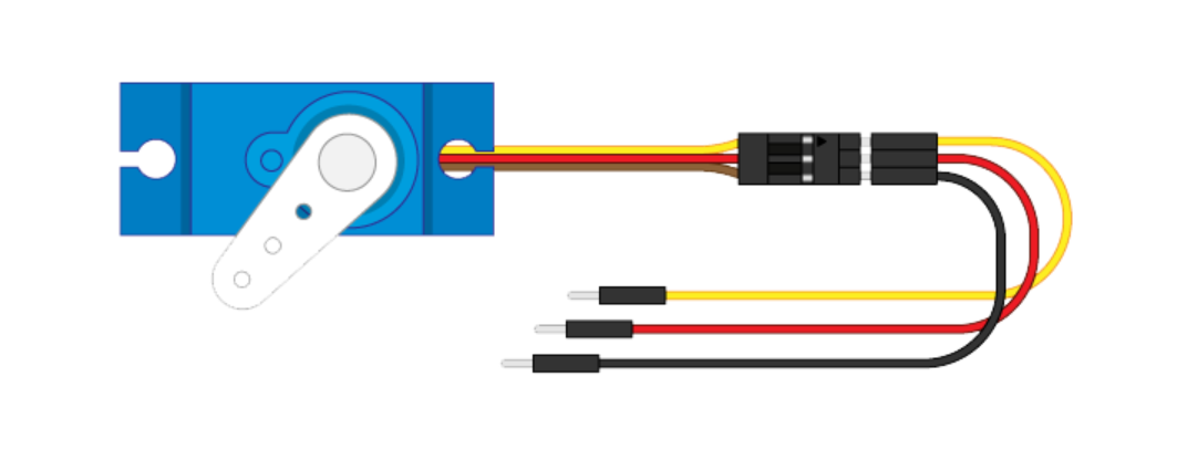 Use a little bit of either hot glue or electrical tape to connect the joints together. This helps prevent it unplugging itself later from motion.
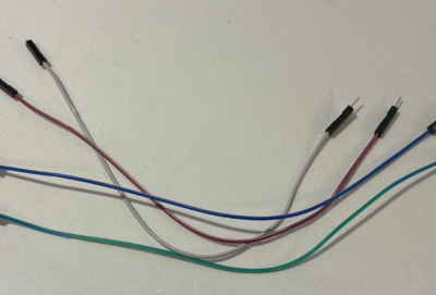
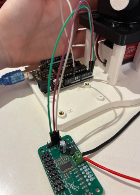
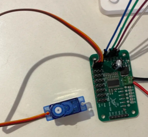
 They should look like this:
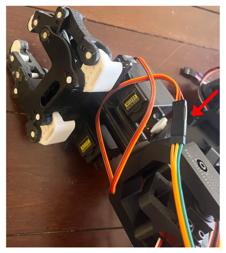
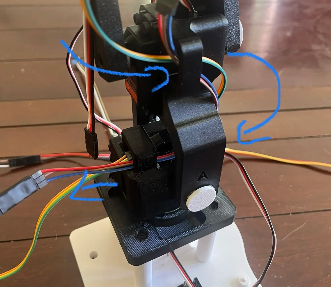
Start looping from top down.
Start with the claws then go to L4, L3, L2, and L1. T1 gets plugged directly into the PCB. This is for the two claw wires only, the steps are the exact same for the rest!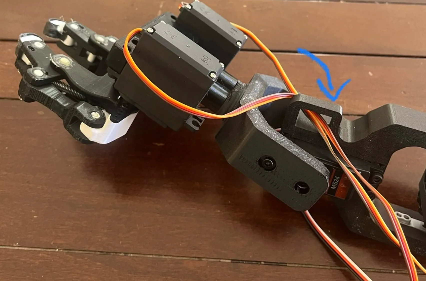
╰┈➤ Go to Step 5: Quick Check
Quick Check!
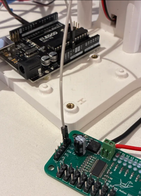
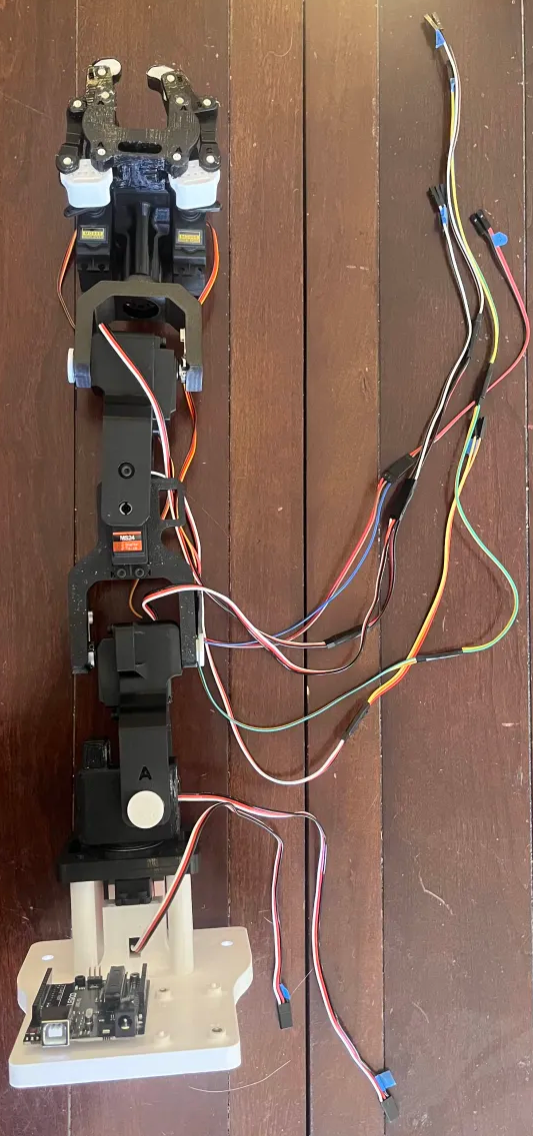
Not everything is plugged in yet (i.e into the PCB/Arduino), but this is roughly the end result we want to shoot for.
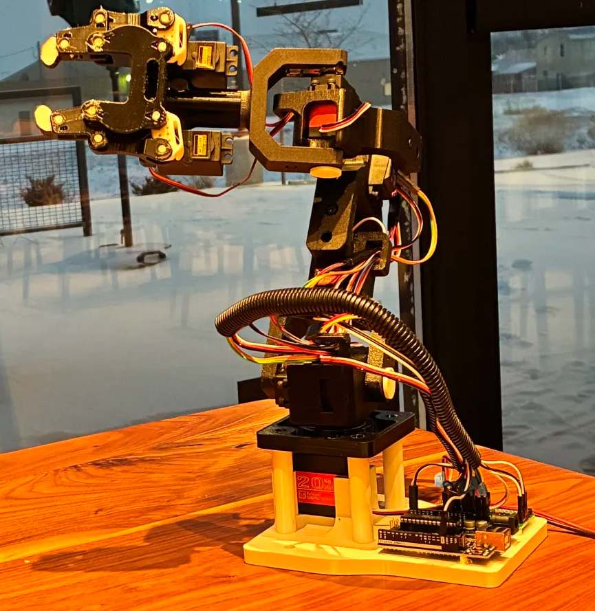
Important: Turn off power, and unplug everything before you wire anything in!!
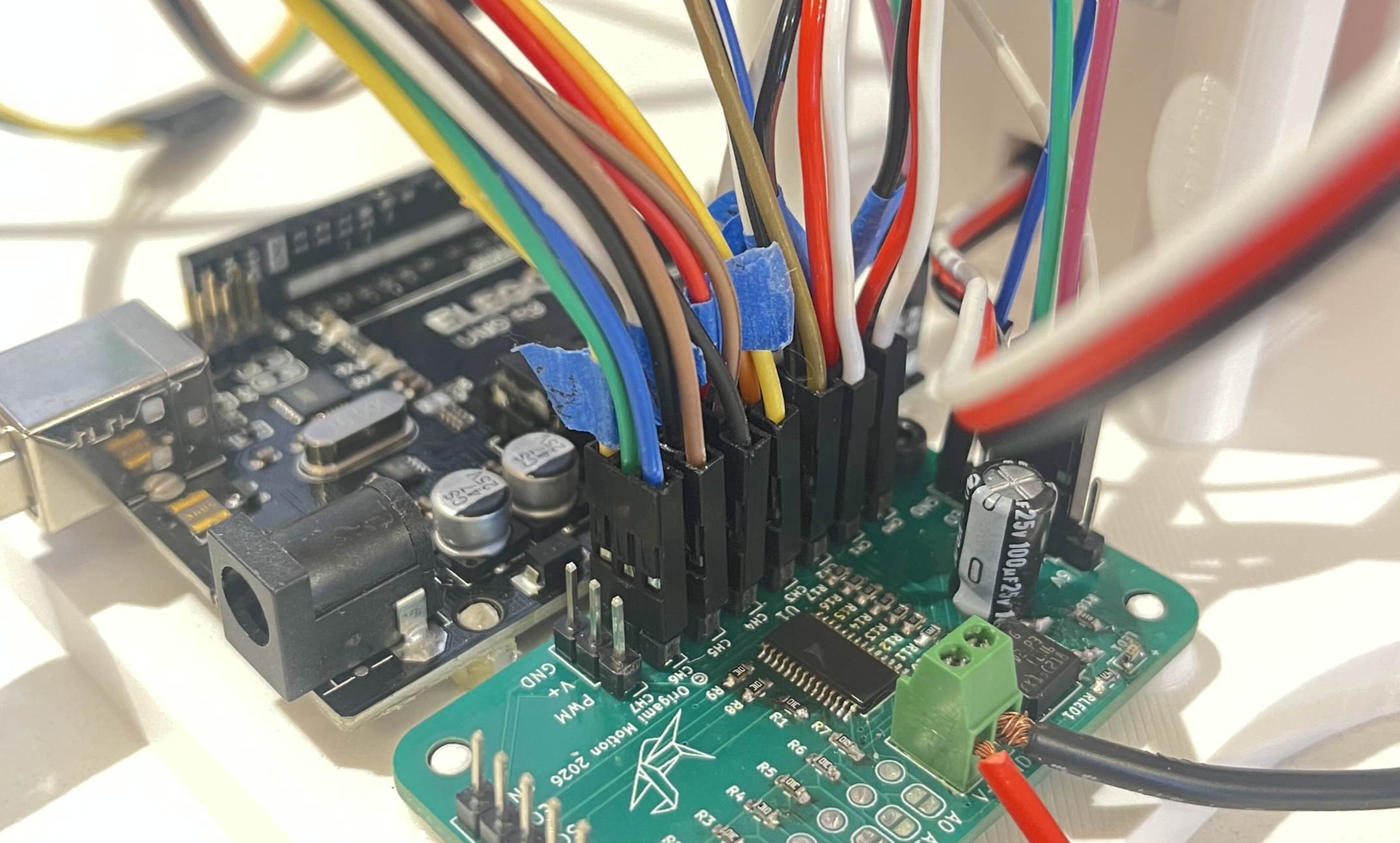
Connect the female wires to the channels.
Remember how you labeled all of the wires earlier (L4/GND, L2/GND etc etc)? You will now go servo by servo BOTTOM TO TOP, and plug in each of the servos. T1 goes into CHO L1 goes into CH1 L2 goes into CH2 L3 goes into CH3 L4 goes into CH4 LC (Left Claw) goes into CH5 RC(Right Claw) goes into CH6╰┈➤ Go to Step 2: Quick Check
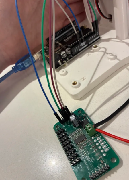
Quick Check!
Should look like this:
MAKE SURE THE WIRES ARE ACTUALLY FULLY PLUGGED IN. If at any point you start having issues with the control/performance of the servos, you might have loose connections.
You're welcome to zip tie the wires together a little, but keep the wires free for trouble shooting as needed. It's good for the wires to have some slack as well and room to turn without straining the wires too much.
Once you have confirmed full function, and everything works as expected, you can go back and hot glue the connections in place.
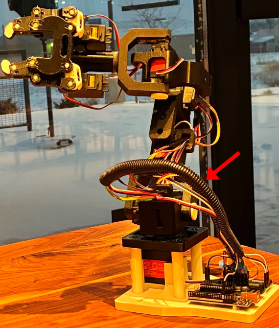
You can also use something like this split wire protection tube to slip all the dangling wires into.