Chapter 4: L4 - Claw Assembly

--
1. Tools Necessary For This Chapter


⬢ For this chapter, please prepare:

M2.5 Allen Key for attaching the servo and the housing block. (included)
M1.5 Allen Key for attaching the set screw. (included)
Phillips Screwdriver for attaching the pinion gear screws. (included).
Laptop for programming the servo position.
Soldering Iron for attaching heat inserts.
Wire Cutters for trimming servos as needed.

--
2. Gather Parts


⬢ For this chapter, please gather the following bags and parts. (Some may still be out from Chapter 3). Also have your progress from Chapter 3 ready!:

--
3. Install the Servo Horn onto Link C

The servo horn connects the servo to the linkage.

🛠️ Needed Parts: Metal 25-tooth Servo Horn (1x), M3 Phillips Screw (1x), Link C (1x)

Find the 25-tooth Metal Servo Horn

Find the metal servo horn that looks like this!

Place the Servo Horn Inside Link C

The Servo Horn slides into the slot inside Link C as shown.

📌 Pro Tip: If you have a hard time sliding the servo horn in, you may want a pair of pliers or a clamp.

Attach the Servo Horn

Screw in the Servo Horn with an M3 BOLT.

--
4. Place the L4 Motor in the Housing

The L4 motor is a 20kg motor!

🛠️ Needed Parts: 20kg Servo (1x), M3 Bolts (4x), M3 Washers (4x), Arm Base (1x)

Find the 20-kg Servo

Find the servo that looks like this!

Place the Servo Inside Link B Housing

Slide the 20kg Servo into the Link B Housing that is apart of the B2 linkage.

You've probably noticed that the housing for the next motor is apart of the linkage attached to the shaft of the motor before it. Together they make one part with two primary functions.

Screenshot 2026-01-31 153908

Bolt in the Servo

Attach the Servo Motor using 4x M3 Washers and 4x M3 Bolts. Place the washer between the bolt and the housing.

--
5. Set the Servo Start Position

We're going to set the servo to 90 degrees like last time! We already have the code, we just need to upload it!

Re-Wiring the Test Servo Circuit

🛠️ Needed Parts: Arduino Uno (1x), Arduino Cable (1x), Test Cable (1x), Power Supply (1x), Power Supply Adapter Head (1x), Robot Arm Base (1x)

You guys are going to move your servo wiring from the other servo to the new 40kg one! Follow the steps below! 🙂

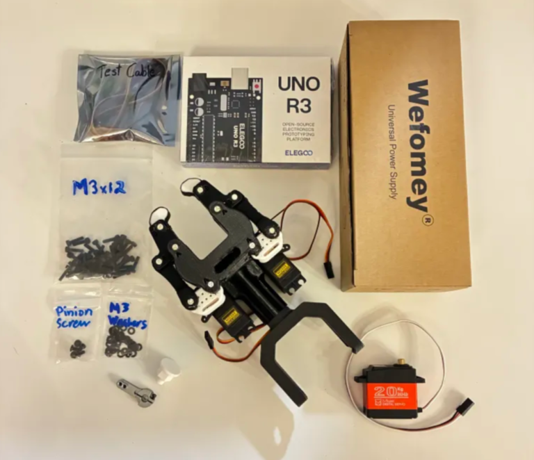
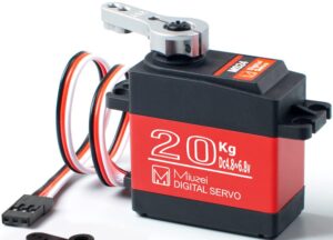
Check your components.

You should have your Arduino, Arduino Cable, Test Cable, Power Supply, Power Supply Adapter Head, and Robot Arm Base all within easy reach. Your Arduino and Power Supply should both be unplugged at this time.

Before You Start: Make sure all power is OFF before connecting or adjusting any components. This step involves live electrical connections. Double-check wiring, move slowly, and keep hands clear when power is applied.

╰┈➤ Proceed to Section 2: About Servo Wires.

A little about servo wires.

Warning: The power supply and Arduino should both be off and unplugged before proceeding.   Every servo has three wires, and each one has a job. Brown or Black = Ground Red = Power Orange / Yellow / White = Signal (PWM)

Wire Servo

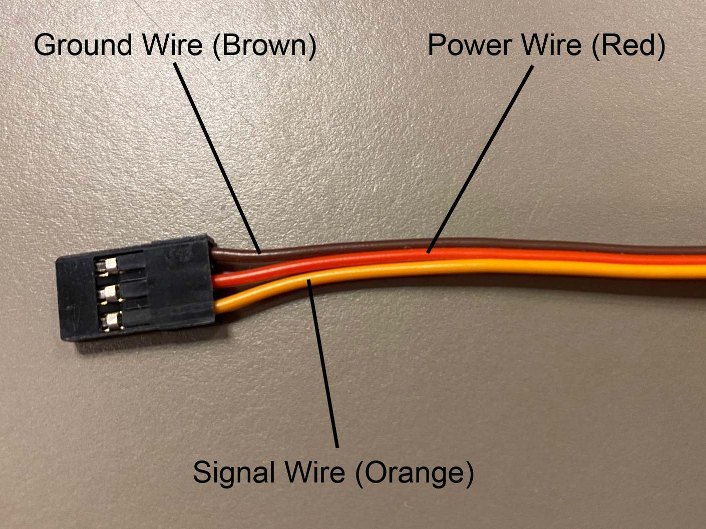
Let’s walk through what each one does and where it goes.

1. Servo Ground Wire (brown or black)

This servo wire will go to ground.

  • This goes into GND on the Arduino...
  • AND into ground on your 6V power supply.

📌 Pro Tip: Your Test Cable has each wire already labeled.

2. Servo Power Wire (red) This wire actually powers the motor inside the servo.
  • This will go into the 6V power supply's positive rail.
  • This should NOT be plugged into the 5V pin on the Arduino.
3. Servo Signal Wire (yellow / orange / white) This wire goes to any digital pin on the Arduino (for example, pin 9). This wire does not power anything. It just carries PWM instructions.

╰┈➤ Proceed to Section 3: Wire The Test Bench.

Let's wire the test bench!

Alright! It's finally time to wire our test bench.

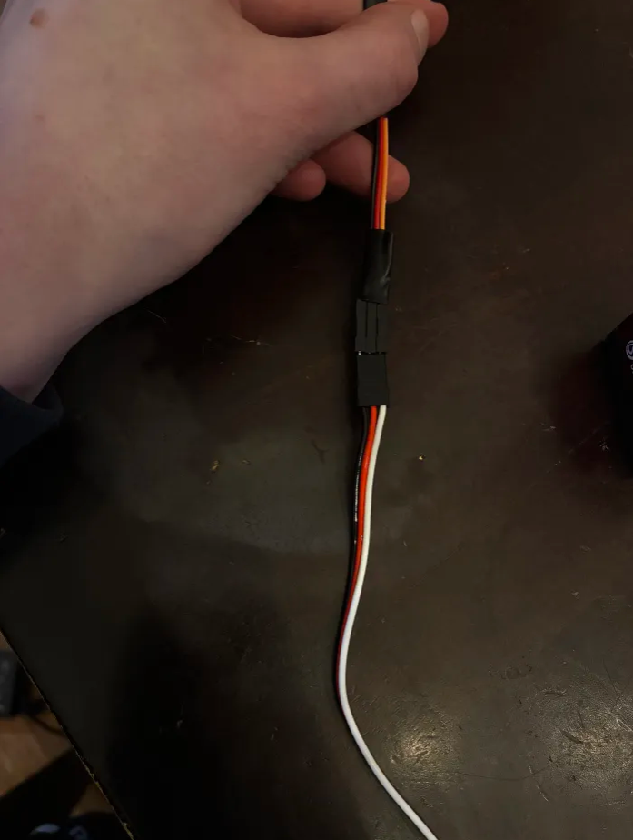
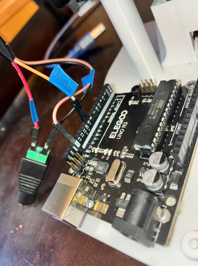
1. Connect the 3-wire side of your Test Cable to the T1 servo. The ground wire of your servo should connect to the black wire on the Test Cable. The power wire of your servo should connect to the red wire on the Test Cable. The signal wire on your servo should connect to the orange wire on the Test Cable.

2. On the 4-wire side of your Test Cable, locate the 6V wire and one of the 2 Ground Wires. Screw the 6V Wire into the Positive (+) side of the Power Supply Adapter Head. Screw the GND Wire into the Negative (-) side of the Power Supply Adapter Head.

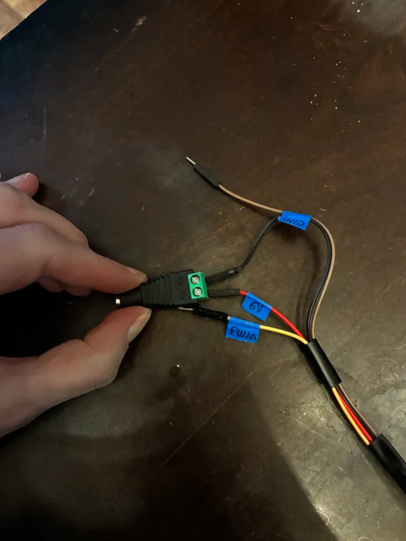
3. Plug the other GND wire into the GND pin of the Arduino. This is for that shared reference point we talked about in Section 4 - About Servo Wires!

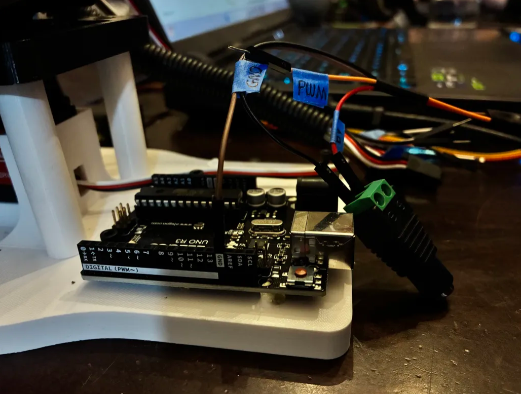
4. Plug the PWM wire into Pin 9 of the Arduino. You could use any digital pin on the Arduino for this, but the code following this will reference Pin 9.

📌 Pro Tip: You could use any of the 13 digital Arduino Pins for this (and it would still work), but the code in this guide will reference Pin 9.

5. All your wires should be plugged in now! Carefully plug the Power Supply output into the Power Supply Adapter Head.

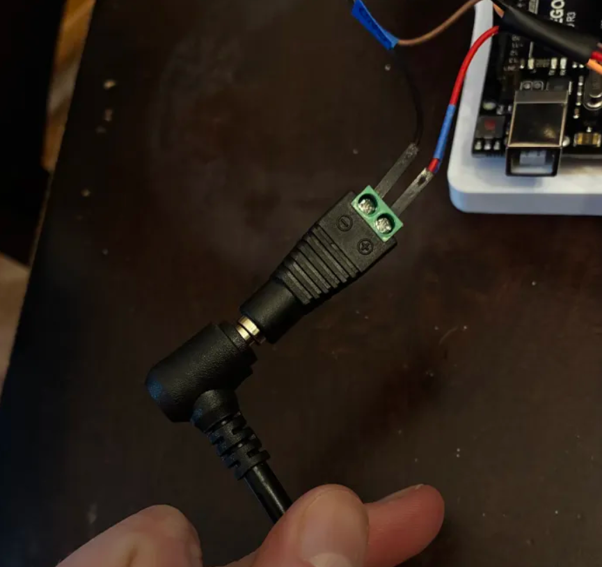
6. Plug your Arduino into your computer's USB port.

7. Plug your Power Supply into the wall. It should kick on to the voltage you set earlier.

Be careful! If you turn on the power supply and see that it has been bumped to a voltage above 6V, immediately turn the knob all the way down. Disconnect the Power Supply Adapter Head and repeat the steps in Section 4 - Set the Power Supply.

Run Your Code!

Plug in your Arduino, open Arduino IDE and run the same script as you did to set the other servo to 90.

Set the Servo to 90 degrees.

In case it got lost in the void, here's that code again to copy and paste!

#include <Servo.h> 
Servo myServo;
      
void setup(){      
      Serial.begin(9600);
      myServo.attach(9);
      myServo.write(90);
}      


void loop(){      
  if (Serial.available()) {
    char cmd = Serial.read();
    switch (cmd) {     
      case 'A':     
      case 'a':     
            myServo.write(0);     
            Serial.println("Servo --> 0 degrees");     
            break;
      case 'B':     
      case 'b':     
            myServo.write(90);     
            Serial.println("Servo --> 90 degrees");     
            break;
      case 'C':     
      case 'c':     
            myServo.write(180);     
            Serial.println("Servo --> 180 degrees");     
            break;     
      default:     
            Serial.println("Unknown command");     
            break;
            }     
      }
}

--
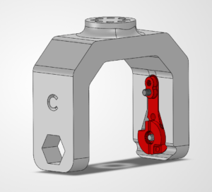
6. Attach the Servo Horn to the Motor

With the servo still energized, we're going to attach the Link C to the L4 Motor!

🛠️ Needed Parts: Link C (1x), Arm Base (1x)

Attach the Link C to the Servo

Important: THE SERVO MUST STILL BE PLUGGED IN TO YOUR ARDUINO AND SET TO 90 DEGREES FOR THIS STEP.

Slide the Servo Horn attached to Link C onto the servo. The servo horn has internal threads that will lock onto the servo. It should press fit into place.

You want to place it so that it is facing vertically upwards. It might be a little hard. Line the side with the servo horn first, then strong arm the side with the hex bore in after.

Attach with the Hex Pin

You will then take the hex pin part and slide it into the hex bore slot. If it doesn't stay, feel free to add some hot glue.

Lock the Servo Horn onto the Servo

Once again, take the tiny M3 Phillips screw and lock the servo horn onto the L4 motor shaft.

Attach Set Screw

Attach the set screw into the side of the servo horn to lock everything in place.

--
7. Attach the Arduino

Take your hot glue gun and let it heat up fully.

Apply a small dap of hot glue onto this square pad and two pins, then quickly slide the Arduino onto the pad, making sure you align it with the pins.

Take 2x M3x12 bolts and screw in the arduino

--
8. Haribo!

You my now consume the third pile of gummies.

Did you know that you can grow a chubby gummy bear? Leave one in water overnight and it’ll swell to several times its size (osmosis, baby).

Osmosis is when water moves into or out of something to balance water levels. Water automatically moves from places with more to places with less.

You're all set! On to Chapter 5: Solder the Practice PCB! ᯓ✈︎