What is a heat-set insert?
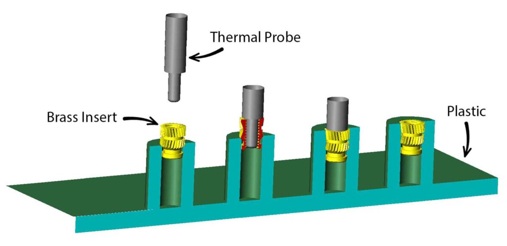
A heat-set insert is a small metal threaded sleeve designed to be permanently installed in a plastic part. When heated, it melts the surrounding plastic slightly so the plastic flows around the insert’s knurls. Once cooled, it creates strong, reusable threads that are much more durable than screwing directly into plastic.
╰┈➤ Go to Step 2: Check Your Workspace
Check your workspace first.
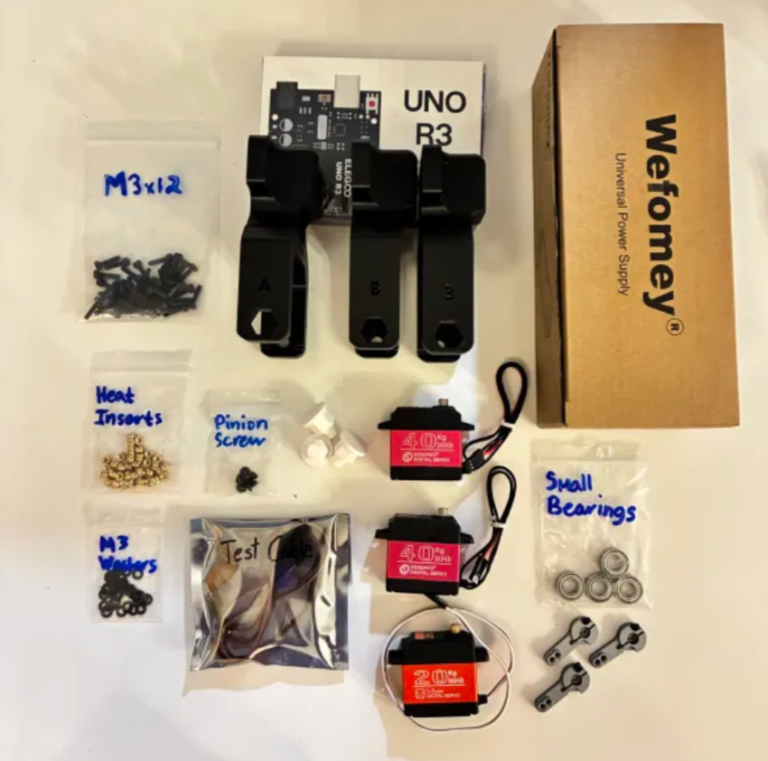
When working with heated objects, first make sure your workspace is level and clean. Gather the parts you will be putting heat inserts into, and the heat inserts themselves.
Before You Start: Make sure you are working in a ventilated workspace. Working with soldering irons or heated tools is a burn hazard.
╰┈➤ Go to Step 3: Soldering Iron Setup
Set up your soldering iron.
Set the temperature: Set soldering iron to ~600°F for PETG-CF, the 3D printed filament the arm components are printed in.
Preheat the iron: Allow the soldering iron to fully heat.
╰┈➤ Go to Step 4: Place the Insert
Place the Insert.
Insert the heat-set insert into the hole by hand. The small side of the insert goes into the hole and will fit into place. Ensure it is straight.
Warning: If your heat inserts are not straight, you may end up with crooked threads and assembly may not be possible.
╰┈➤ Go to Step 5: Heat!
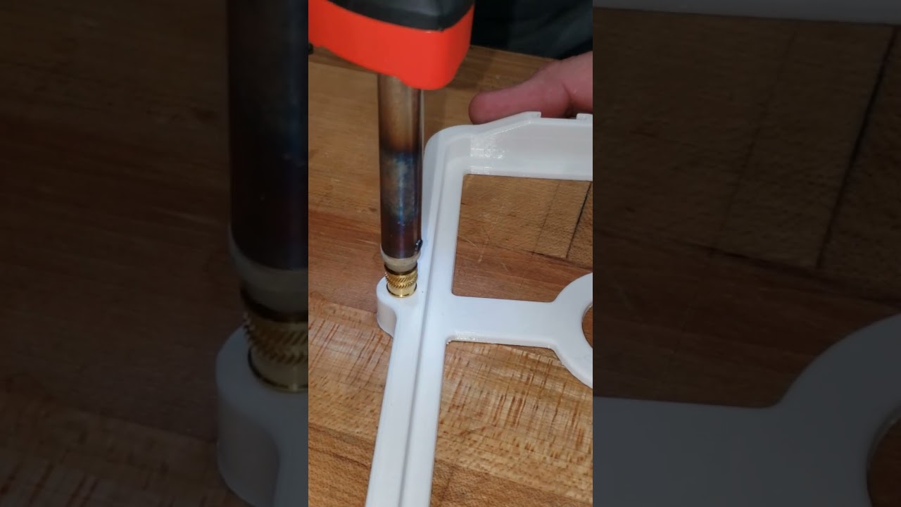
Heat!
Place the iron tip of the heated soldering iron on the insert. Apply slow, light pressure as the plastic softens.
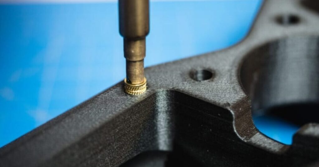
Keep the insert vertical at all times. Stop and realign if it begins to tilt. Press until the insert is just a little below the surface.
📝Why? This is because when the plastic cools down, it pushes the heat insert back up and it will extrude past the surface. You want it to be flat.
When it is done, lift the iron straight up. Do not twist.
📌 Pro Tip: Press a flat metal object (like a hand file) on top of the heat insert as it cools down. Do not install a screw until fully cooled.
╰┈➤ Go to Step 6: Quick Check
Quick Check!
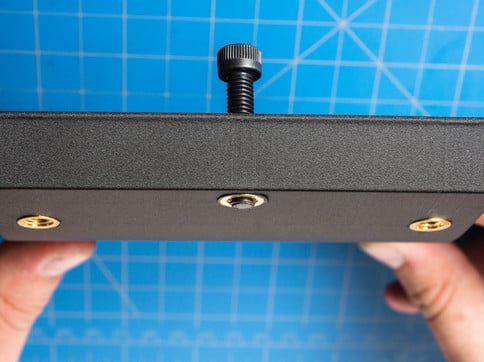
Insert should be straight, flush, and firmly locked in place. Thread a screw a little in by hand to confirm it threads in easily.
╰┈➤ Go to Step 7: Feeling Lost?
Feeling lost?
Watch this video for a great explanation/demo of installing a heat insert using a soldering iron.
Click to watch a short example video.


Check your components.
You should have your Arduino, Arduino Cable, Test Cable, Power Supply, Power Supply Adapter Head, and Robot Arm Base all within easy reach. Your Arduino and Power Supply should both be unplugged at this time.
Before You Start: Make sure all power is OFF before connecting or adjusting any components. This step involves live electrical connections. Double-check wiring, move slowly, and keep hands clear when power is applied.╰┈➤ Proceed to Section 2: About Servo Wires.
A little about servo wires.
Warning: The power supply and Arduino should both be off and unplugged before proceeding. Every servo has three wires, and each one has a job. Brown or Black = Ground Red = Power Orange / Yellow / White = Signal (PWM)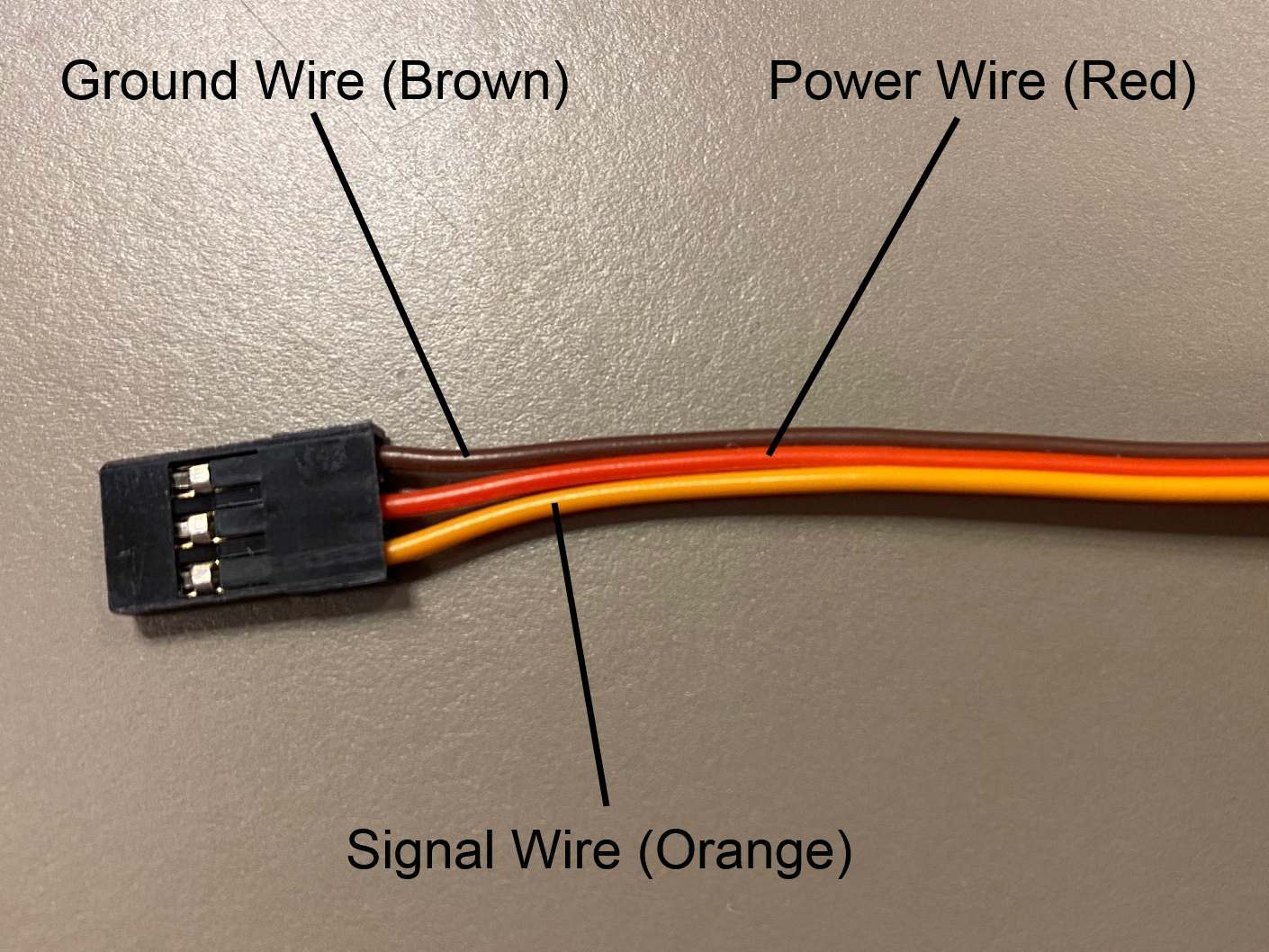
Let’s walk through what each one does and where it goes.
1. Servo Ground Wire (brown or black)This servo wire will go to ground.
- This goes into GND on the Arduino...
- AND into ground on your 6V power supply.
📌 Pro Tip: Your Test Cable has each wire already labeled.
2. Servo Power Wire (red) This wire actually powers the motor inside the servo.- This will go into the 6V power supply's positive rail.
- This should NOT be plugged into the 5V pin on the Arduino.
╰┈➤ Proceed to Section 3: Wire The Test Bench.
Let's wire the test bench!
Alright! It's finally time to wire our test bench.
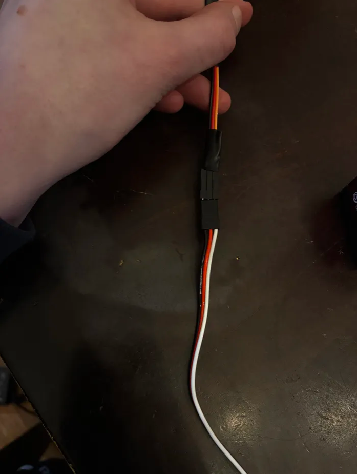
1. Connect the 3-wire side of your Test Cable to the T1 servo. The ground wire of your servo should connect to the black wire on the Test Cable. The power wire of your servo should connect to the red wire on the Test Cable. The signal wire on your servo should connect to the orange wire on the Test Cable.
2. On the 4-wire side of your Test Cable, locate the 6V wire and one of the 2 Ground Wires. Screw the 6V Wire into the Positive (+) side of the Power Supply Adapter Head. Screw the GND Wire into the Negative (-) side of the Power Supply Adapter Head.
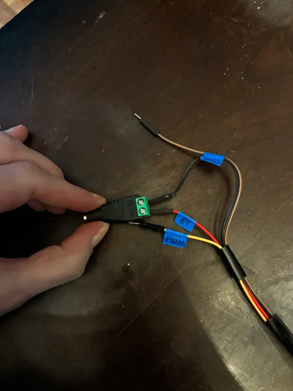
3. Plug the other GND wire into the GND pin of the Arduino. This is for that shared reference point we talked about in Section 4 - About Servo Wires!
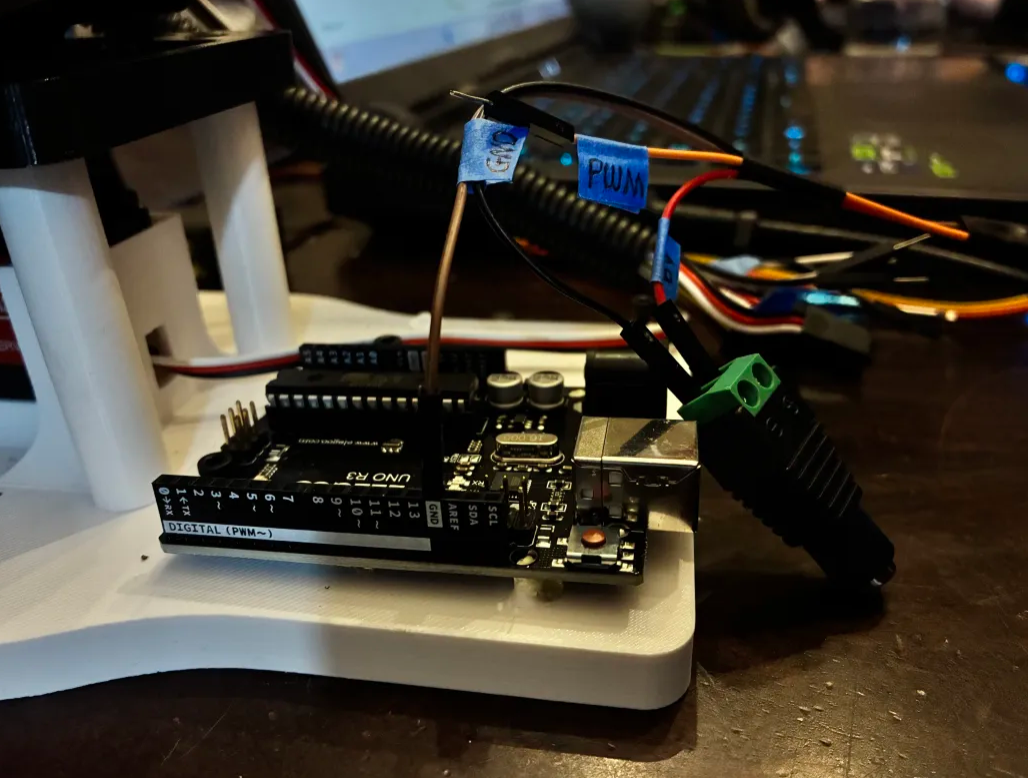
4. Plug the PWM wire into Pin 9 of the Arduino. You could use any digital pin on the Arduino for this, but the code following this will reference Pin 9.
📌 Pro Tip: You could use any of the 13 digital Arduino Pins for this (and it would still work), but the code in this guide will reference Pin 9.
5. All your wires should be plugged in now! Carefully plug the Power Supply output into the Power Supply Adapter Head. 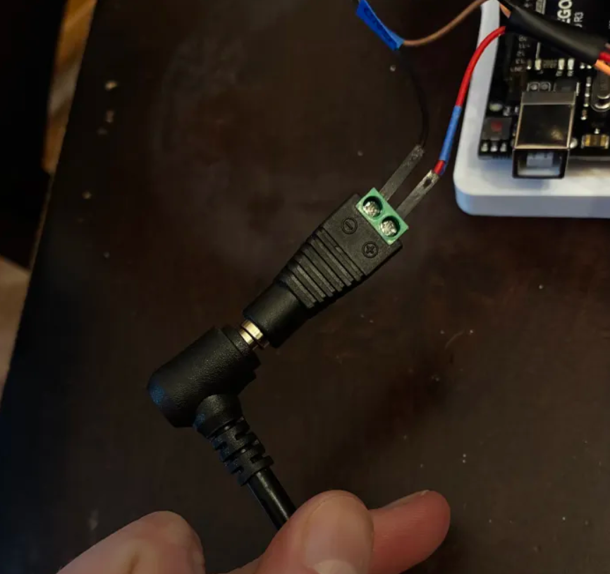
6. Plug your Arduino into your computer's USB port.
7. Plug your Power Supply into the wall. It should kick on to the voltage you set earlier.
Be careful! If you turn on the power supply and see that it has been bumped to a voltage above 6V, immediately turn the knob all the way down. Disconnect the Power Supply Adapter Head and repeat the steps in Section 4 - Set the Power Supply.
--
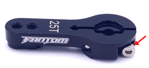
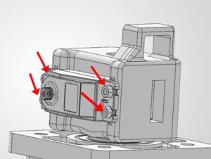
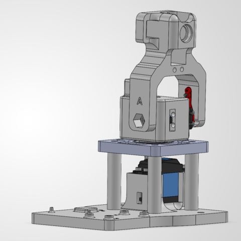
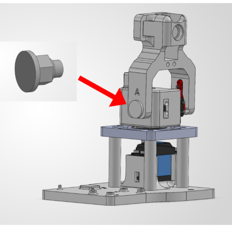
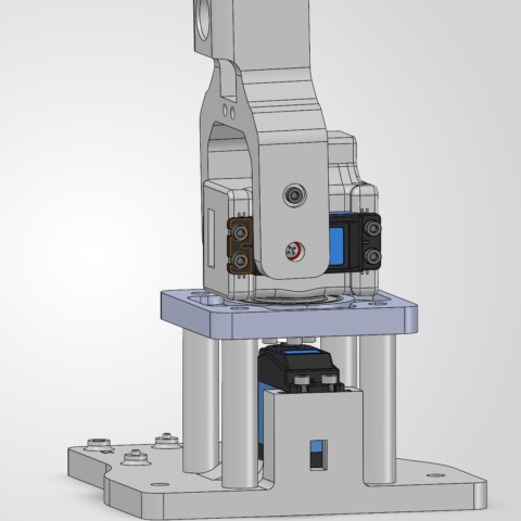
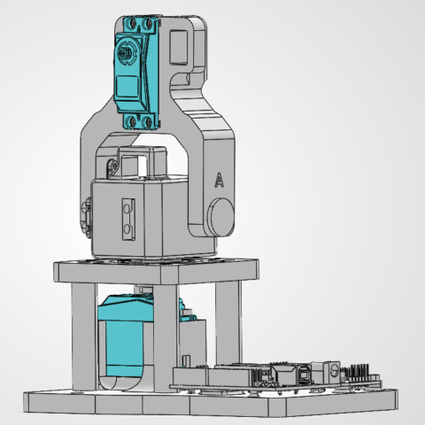
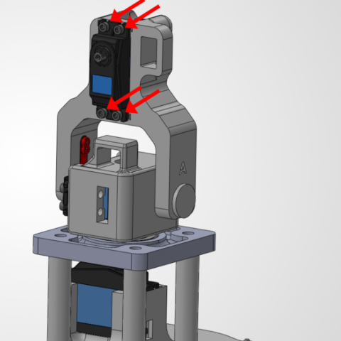
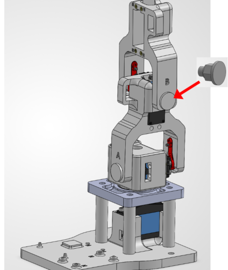
8. Attach the Servo Horn to the Motor
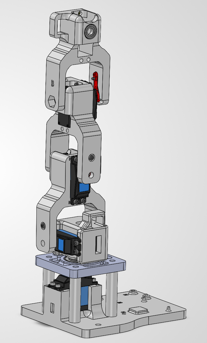
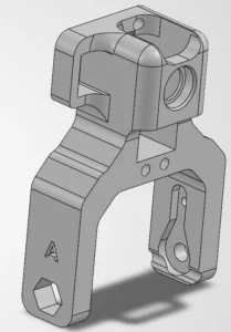
With the servo still energized, we're going to attach the Link A to the L1 Motor!
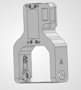
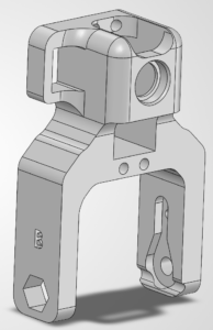
 Needed Parts: Link A (1x), Arm Base (1x)
What is a heat-set insert?
A heat-set insert is a small metal threaded sleeve designed to be permanently installed in a plastic part. When heated, it melts the surrounding plastic slightly so the plastic flows around the insert’s knurls. Once cooled, it creates strong, reusable threads that are much more durable than screwing directly into plastic.
╰┈➤ Go to Step 2: Check Your Workspace
Check your workspace first.
When working with heated objects, first make sure your workspace is level and clean. Gather the parts you will be putting heat inserts into, and the heat inserts themselves.
Before You Start: Make sure you are working in a ventilated workspace. Working with soldering irons or heated tools is a burn hazard.
╰┈➤ Go to Step 3: Soldering Iron Setup
Set up your soldering iron.
Set the temperature: Set soldering iron to ~600°F for PETG-CF, the 3D printed filament the arm components are printed in.
Preheat the iron: Allow the soldering iron to fully heat.
╰┈➤ Go to Step 4: Place the Insert
Place the Insert.
Insert the heat-set insert into the hole by hand. The small side of the insert goes into the hole and will fit into place. Ensure it is straight.
Warning: If your heat inserts are not straight, you may end up with crooked threads and assembly may not be possible.
╰┈➤ Go to Step 5: Heat!
Heat!
Place the iron tip of the heated soldering iron on the insert. Apply slow, light pressure as the plastic softens.
Keep the insert vertical at all times. Stop and realign if it begins to tilt. Press until the insert is just a little below the surface.
📝Why? This is because when the plastic cools down, it pushes the heat insert back up and it will extrude past the surface. You want it to be flat.
When it is done, lift the iron straight up. Do not twist.
📌 Pro Tip: Press a flat metal object (like a hand file) on top of the heat insert as it cools down. Do not install a screw until fully cooled.
╰┈➤ Go to Step 6: Quick Check
Quick Check!
Insert should be straight, flush, and firmly locked in place. Thread a screw a little in by hand to confirm it threads in easily.
╰┈➤ Go to Step 7: Feeling Lost?
Feeling lost?
Watch this video for a great explanation/demo of installing a heat insert using a soldering iron.
Click to watch a short example video.
Check your components.
You should have your Arduino, Arduino Cable, Test Cable, Power Supply, Power Supply Adapter Head, and Robot Arm Base all within easy reach. Your Arduino and Power Supply should both be unplugged at this time.
Before You Start: Make sure all power is OFF before connecting or adjusting any components. This step involves live electrical connections. Double-check wiring, move slowly, and keep hands clear when power is applied.╰┈➤ Proceed to Section 2: About Servo Wires.
A little about servo wires.
Warning: The power supply and Arduino should both be off and unplugged before proceeding. Every servo has three wires, and each one has a job. Brown or Black = Ground Red = Power Orange / Yellow / White = Signal (PWM)
Let’s walk through what each one does and where it goes.
1. Servo Ground Wire (brown or black)This servo wire will go to ground.
- This goes into GND on the Arduino...
- AND into ground on your 6V power supply.
📌 Pro Tip: Your Test Cable has each wire already labeled.
2. Servo Power Wire (red) This wire actually powers the motor inside the servo.- This will go into the 6V power supply's positive rail.
- This should NOT be plugged into the 5V pin on the Arduino.
╰┈➤ Proceed to Section 3: Wire The Test Bench.
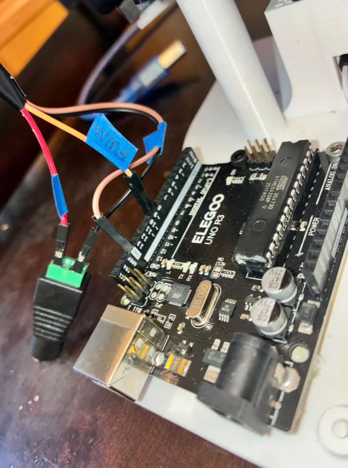
Let's wire the test bench!
Alright! It's finally time to wire our test bench.
1. Connect the 3-wire side of your Test Cable to the T1 servo. The ground wire of your servo should connect to the black wire on the Test Cable. The power wire of your servo should connect to the red wire on the Test Cable. The signal wire on your servo should connect to the orange wire on the Test Cable.
2. On the 4-wire side of your Test Cable, locate the 6V wire and one of the 2 Ground Wires. Screw the 6V Wire into the Positive (+) side of the Power Supply Adapter Head. Screw the GND Wire into the Negative (-) side of the Power Supply Adapter Head.
3. Plug the other GND wire into the GND pin of the Arduino. This is for that shared reference point we talked about in Section 4 - About Servo Wires!
4. Plug the PWM wire into Pin 9 of the Arduino. You could use any digital pin on the Arduino for this, but the code following this will reference Pin 9.
📌 Pro Tip: You could use any of the 13 digital Arduino Pins for this (and it would still work), but the code in this guide will reference Pin 9.
5. All your wires should be plugged in now! Carefully plug the Power Supply output into the Power Supply Adapter Head.
6. Plug your Arduino into your computer's USB port.
7. Plug your Power Supply into the wall. It should kick on to the voltage you set earlier.
Be careful! If you turn on the power supply and see that it has been bumped to a voltage above 6V, immediately turn the knob all the way down. Disconnect the Power Supply Adapter Head and repeat the steps in Section 4 - Set the Power Supply.
--
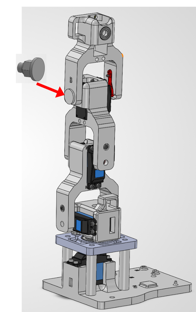
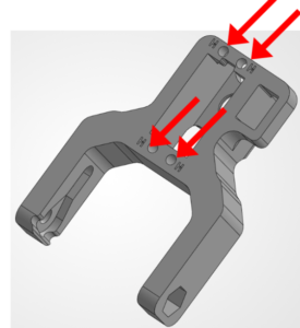
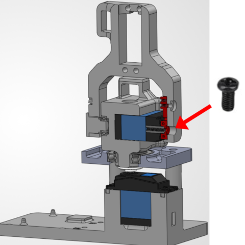
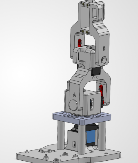
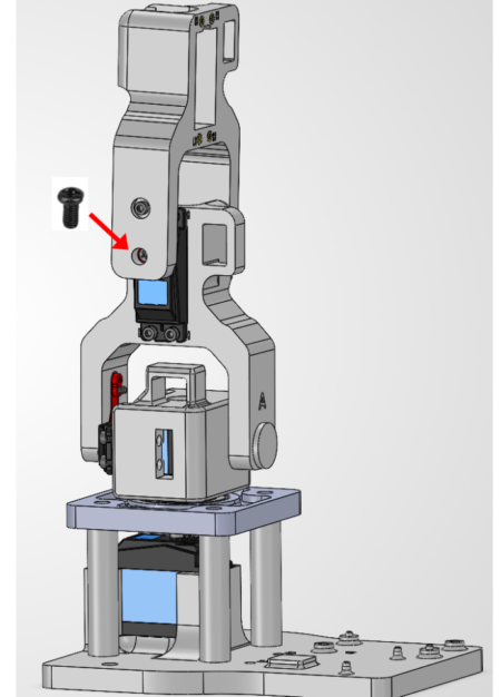
15. Attach Link B1 to the L2 servo.
With the servo still energized, we're going to attach the Link B to the L2 Motor!
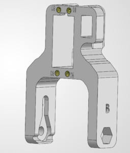
Needed Parts: Link B (1x), Arm Base (1x)
What is a heat-set insert?
A heat-set insert is a small metal threaded sleeve designed to be permanently installed in a plastic part. When heated, it melts the surrounding plastic slightly so the plastic flows around the insert’s knurls. Once cooled, it creates strong, reusable threads that are much more durable than screwing directly into plastic.
╰┈➤ Go to Step 2: Check Your Workspace
Check your workspace first.
When working with heated objects, first make sure your workspace is level and clean. Gather the parts you will be putting heat inserts into, and the heat inserts themselves.
Before You Start: Make sure you are working in a ventilated workspace. Working with soldering irons or heated tools is a burn hazard.
╰┈➤ Go to Step 3: Soldering Iron Setup
Set up your soldering iron.
Set the temperature: Set soldering iron to ~600°F for PETG-CF, the 3D printed filament the arm components are printed in.
Preheat the iron: Allow the soldering iron to fully heat.
╰┈➤ Go to Step 4: Place the Insert
Place the Insert.
Insert the heat-set insert into the hole by hand. The small side of the insert goes into the hole and will fit into place. Ensure it is straight.
Warning: If your heat inserts are not straight, you may end up with crooked threads and assembly may not be possible.
╰┈➤ Go to Step 5: Heat!
Heat!
Place the iron tip of the heated soldering iron on the insert. Apply slow, light pressure as the plastic softens.
Keep the insert vertical at all times. Stop and realign if it begins to tilt. Press until the insert is just a little below the surface.
📝Why? This is because when the plastic cools down, it pushes the heat insert back up and it will extrude past the surface. You want it to be flat.
When it is done, lift the iron straight up. Do not twist.
📌 Pro Tip: Press a flat metal object (like a hand file) on top of the heat insert as it cools down. Do not install a screw until fully cooled.
╰┈➤ Go to Step 6: Quick Check
Quick Check!
Insert should be straight, flush, and firmly locked in place. Thread a screw a little in by hand to confirm it threads in easily.
╰┈➤ Go to Step 7: Feeling Lost?
Feeling lost?
Watch this video for a great explanation/demo of installing a heat insert using a soldering iron.
Click to watch a short example video.
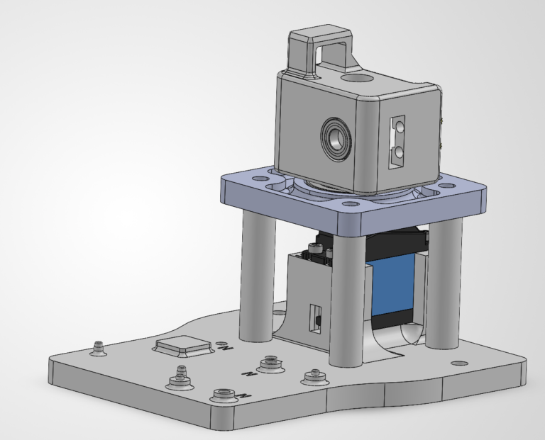
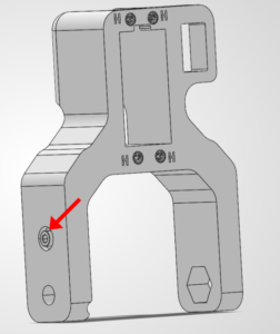
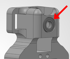
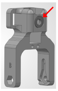
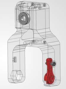
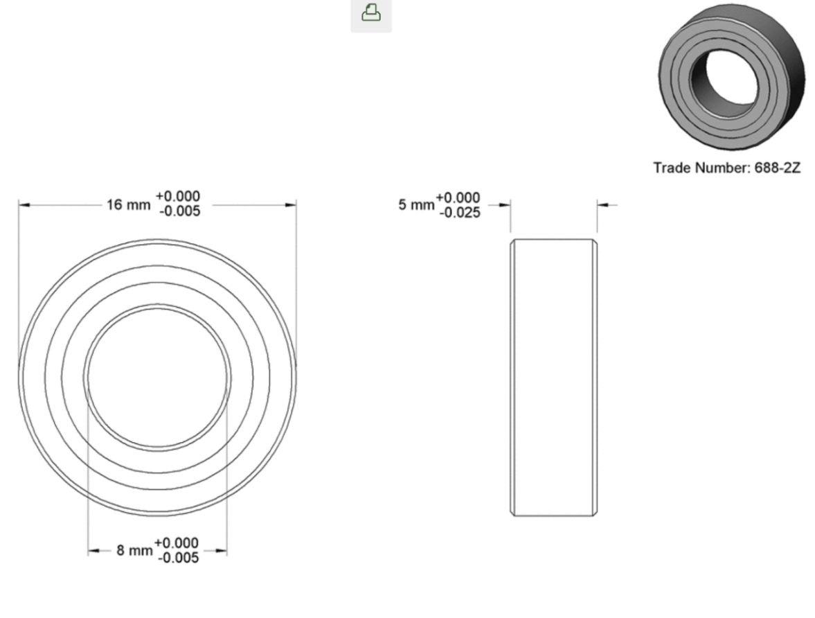
Find the 688-2Z Small Bearing
This is the only bearing designated in Chapter 3 bags. It is a steel shielded ball bearing that looks like this.

Check your components.
You should have your Arduino, Arduino Cable, Test Cable, Power Supply, Power Supply Adapter Head, and Robot Arm Base all within easy reach. Your Arduino and Power Supply should both be unplugged at this time.
Before You Start: Make sure all power is OFF before connecting or adjusting any components. This step involves live electrical connections. Double-check wiring, move slowly, and keep hands clear when power is applied.╰┈➤ Proceed to Section 2: About Servo Wires.
A little about servo wires.
Warning: The power supply and Arduino should both be off and unplugged before proceeding. Every servo has three wires, and each one has a job. Brown or Black = Ground Red = Power Orange / Yellow / White = Signal (PWM)
Let’s walk through what each one does and where it goes.
1. Servo Ground Wire (brown or black)This servo wire will go to ground.
- This goes into GND on the Arduino...
- AND into ground on your 6V power supply.
📌 Pro Tip: Your Test Cable has each wire already labeled.
2. Servo Power Wire (red) This wire actually powers the motor inside the servo.- This will go into the 6V power supply's positive rail.
- This should NOT be plugged into the 5V pin on the Arduino.
╰┈➤ Proceed to Section 3: Wire The Test Bench.
Let's wire the test bench!
Alright! It's finally time to wire our test bench.
1. Connect the 3-wire side of your Test Cable to the T1 servo. The ground wire of your servo should connect to the black wire on the Test Cable. The power wire of your servo should connect to the red wire on the Test Cable. The signal wire on your servo should connect to the orange wire on the Test Cable.
2. On the 4-wire side of your Test Cable, locate the 6V wire and one of the 2 Ground Wires. Screw the 6V Wire into the Positive (+) side of the Power Supply Adapter Head. Screw the GND Wire into the Negative (-) side of the Power Supply Adapter Head.
3. Plug the other GND wire into the GND pin of the Arduino. This is for that shared reference point we talked about in Section 4 - About Servo Wires!
4. Plug the PWM wire into Pin 9 of the Arduino. You could use any digital pin on the Arduino for this, but the code following this will reference Pin 9.
📌 Pro Tip: You could use any of the 13 digital Arduino Pins for this (and it would still work), but the code in this guide will reference Pin 9.
5. All your wires should be plugged in now! Carefully plug the Power Supply output into the Power Supply Adapter Head.
6. Plug your Arduino into your computer's USB port.
7. Plug your Power Supply into the wall. It should kick on to the voltage you set earlier.
Be careful! If you turn on the power supply and see that it has been bumped to a voltage above 6V, immediately turn the knob all the way down. Disconnect the Power Supply Adapter Head and repeat the steps in Section 4 - Set the Power Supply.
--
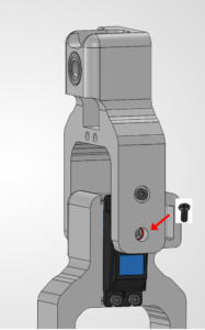
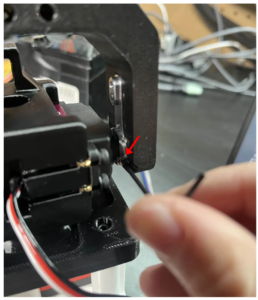
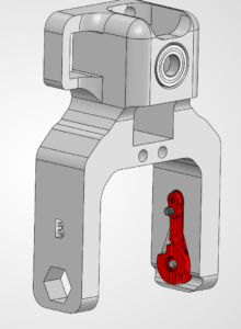
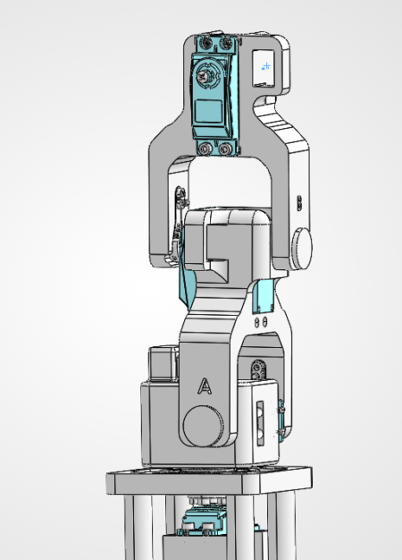
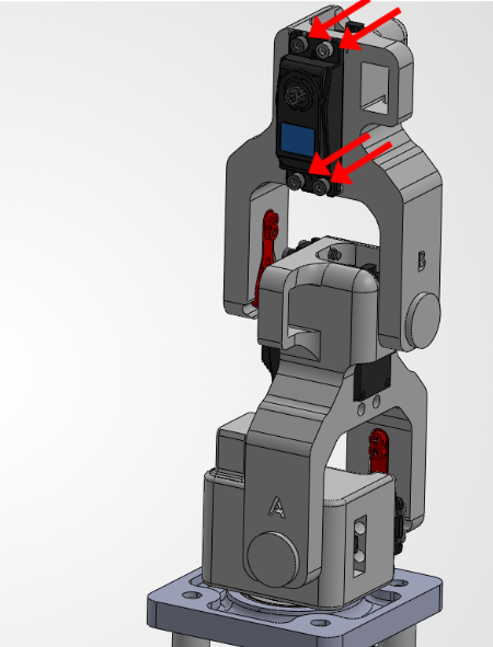
21. Attach the Link B #2 to the Servo
With the servo still energized, we're going to attach the Link B to the L3 Motor!
Needed Parts: Link B #2 (1x), Arm Base (1x)