Chapter 2: Base & Turret Assembly

--
1. Tools Necessary For This Chapter


⬢ For this chapter, please prepare:

M2.5 Allen Key for attaching the servo and the housing block. (included)
M1.5 Allen Key for attaching the set screw. (included)
Phillips Screwdriver for attaching the pinion gear screws.
Laptop for programming the servo position.
Soldering Iron for attaching heat inserts.
Wire Cutters for trimming servos as needed.

--
2. Gather Parts


⬢ For this chapter, please gather the following bags and parts:

--
3. Install Heat Inserts into the Base Plate, Standoffs, and L1 Housing Block

Let's get started with heat inserts! Follow the guide below to learn how to install them.

How To Install Heat Inserts

What is a heat-set insert?

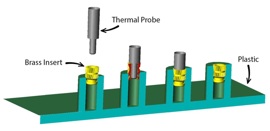
A heat-set insert is a small metal threaded sleeve designed to be permanently installed in a plastic part. When heated, it melts the surrounding plastic slightly so the plastic flows around the insert’s knurls. Once cooled, it creates strong, reusable threads that are much more durable than screwing directly into plastic.

╰┈➤ Go to Step 2: Check Your Workspace

Check your workspace first.

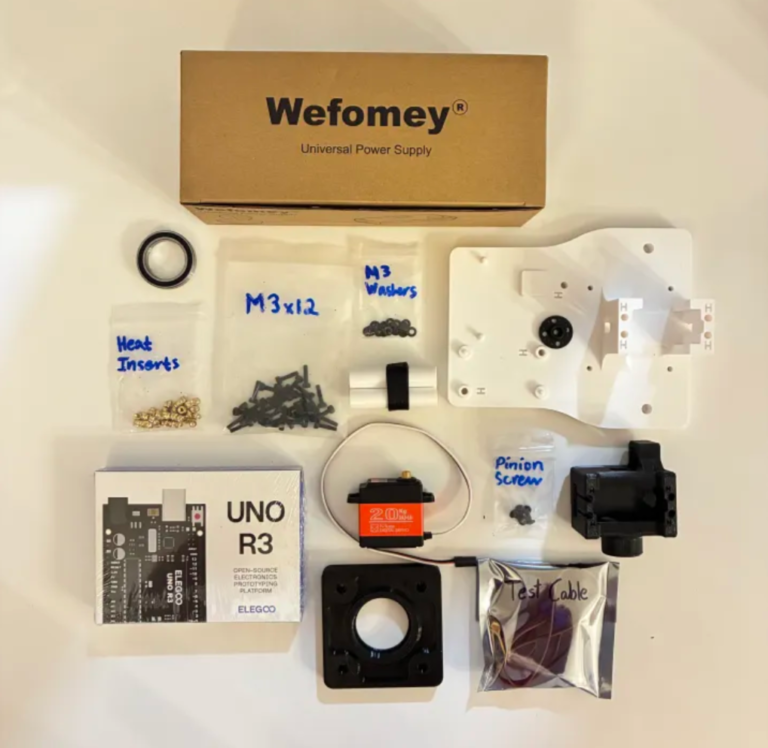
When working with heated objects, first make sure your workspace is level and clean. Gather the parts you will be putting heat inserts into, and the heat inserts themselves.

Before You Start: Make sure you are working in a ventilated workspace. Working with soldering irons or heated tools is a burn hazard.

╰┈➤ Go to Step 3: Soldering Iron Setup

Set up your soldering iron.

Set the temperature: Set soldering iron to ~600°F for PETG-CF, the 3D printed filament the arm components are printed in.

Preheat the iron: Allow the soldering iron to fully heat.

╰┈➤ Go to Step 4: Place the Insert
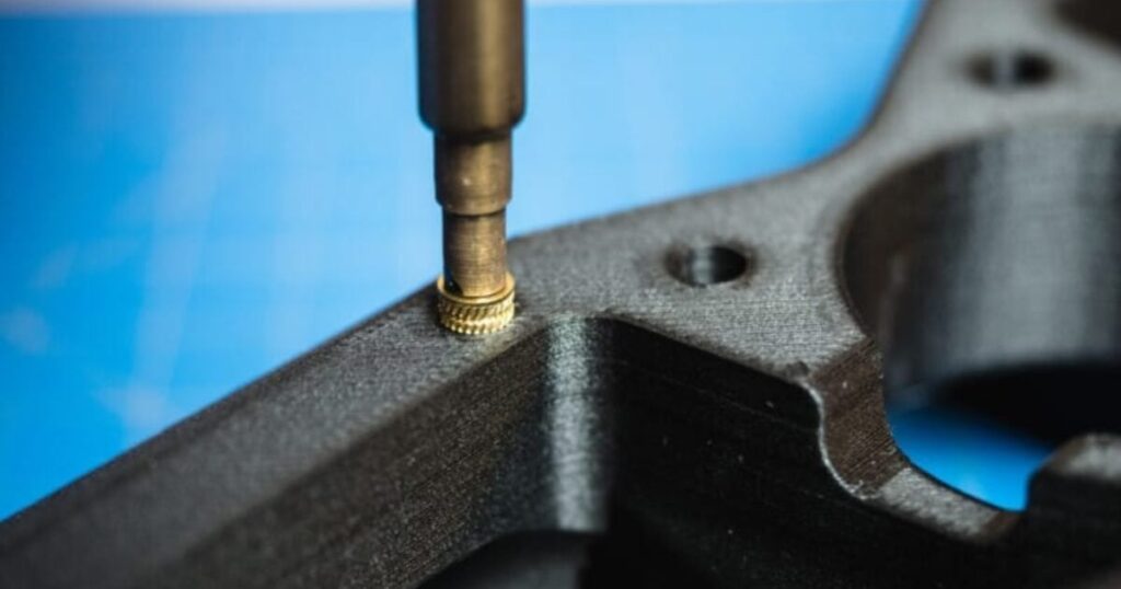
Place the Insert.

Insert the heat-set insert into the hole by hand. The small side of the insert goes into the hole and will fit into place. Ensure it is straight.

Warning: If your heat inserts are not straight, you may end up with crooked threads and assembly may not be possible.

╰┈➤ Go to Step 5: Heat!

Heat!

Place the iron tip of the heated soldering iron on the insert. Apply slow, light pressure as the plastic softens.

Keep the insert vertical at all times. Stop and realign if it begins to tilt. Press until the insert is just a little below the surface.

📝Why? This is because when the plastic cools down, it pushes the heat insert back up and it will extrude past the surface. You want it to be flat.

When it is done, lift the iron straight up. Do not twist.

📌 Pro Tip: Press a flat metal object (like a hand file) on top of the heat insert as it cools down. Do not install a screw until fully cooled.

╰┈➤ Go to Step 6: Quick Check
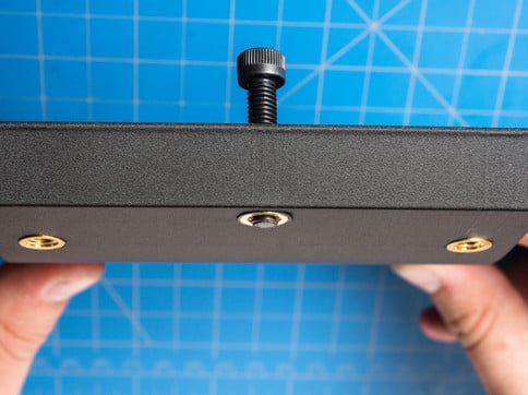
Quick Check!

Insert should be straight, flush, and firmly locked in place. Thread a screw a little in by hand to confirm it threads in easily.

╰┈➤ Go to Step 7: Feeling Lost?

Feeling lost?

Watch this video for a great explanation/demo of installing a heat insert using a soldering iron.


Watch heat-set insert example video

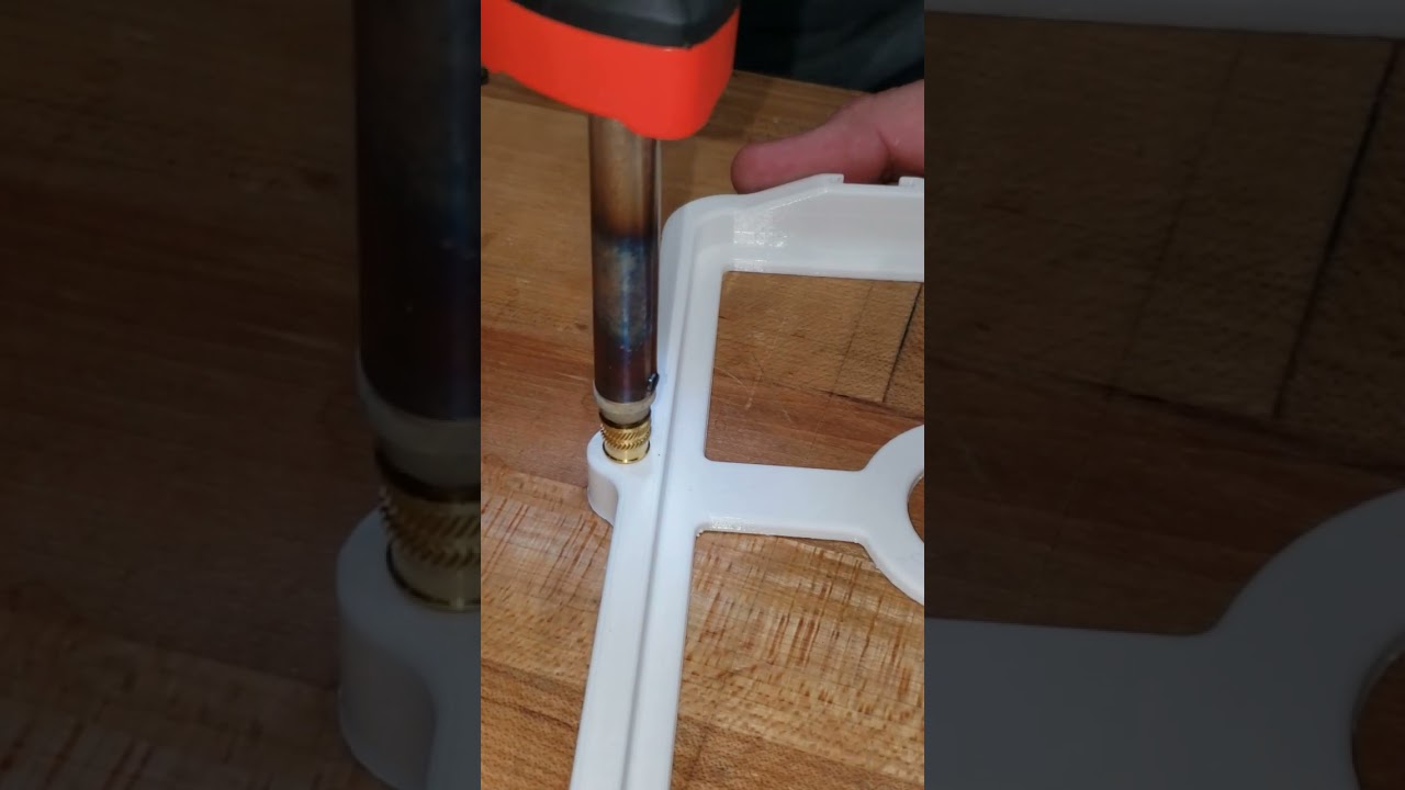
Click to watch a short example video.

Install Heat Inserts into the Base Plate:

🛠️ Needed Parts: Heat Inserts (8x), Base Plate (1x)

The below image is of the base for the robotic arm. Everywhere where there is an 'H' is a hole where a heat insert should be installed. There are 8x heat inserts for the base plate.

The base plate should look like this with all heat inserts installed.

Install Heat Inserts into the Standoffs:

🛠️ Needed Parts: Heat Inserts (8x), Standoffs (4x)

The below image is of the standoffs that connect to the arm base. Heat inserts should go into the holes in the top and bottom of the standoffs.

Each standoff should look like this with both heat inserts installed.

Install Heat Inserts into the L1 Housing Block:

🛠️ Needed Parts: Heat Inserts (8x), L1 Housing Block (1x)

The below image is of the L1 Housing Block. This part will house the L1 control motor. It has 8x Heat Inserts, four in the side, and four in the circular plate at the bottom.

The L1 Housing Block should look like this with all the heat inserts installed.

--
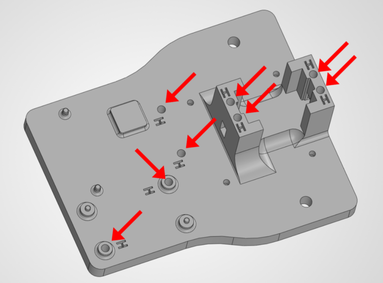
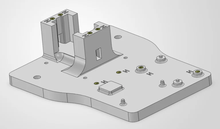
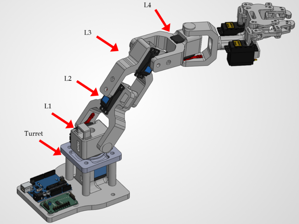
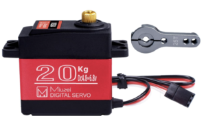
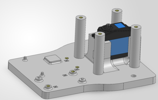
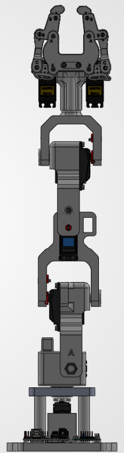
4. Attach the T1 Servo

The T1 servo controls the bottom turret of the arm. It's basically the "lazy susan" of the entire arm. Everything rotates around the bottom turret joint.

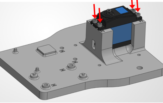
🛠️ Needed Parts: Base Plate (1x), 20 kg-cm Servo (1x), M3 Washers (4x), M3 Bolts (4x)

But How Do We Actually Design This?

Read the guide below to learn how you can design your own arm.

What is Mechanical Engineering/Design?

Mechanical engineering is all about creating motion and manipulating it. That's it. Nothing else. P.S.: You're signing up for long term pain and suffering. See below for a real world scenario.  

╰┈➤ Go to Step 2: Creating Motion

Engineers typically use motors to create motion. A motor is a device that turns electricity into motion, making things spin or move. In our robot arm, we use servo motors. What is a servo motor, and how do we know which one to use? A servo motor is a motor designed for precise control. Instead of just spinning freely, a servo lets you say:

  • “Go to this exact position
  • “Hold this angle
  • Sometimes: “Move at this speed or with this force
A typical hobby servo contains:
  • A DC motor
  • A gearbox (for torque)
  • A position sensor (usually a potentiometer)
  • A control circuit that listens to a signal and corrects itself
So when you command it to 90°, it actively moves there and stays there. Servos are great when you need:
  • Precise positioning (arms, flaps, valves, joints)
  • Repeatable motion
  • Holding a load in place without drifting
They’re not ideal for:
  • High-speed continuous rotation (unless it’s a special type)
  • Very high torque without gearing
Types of servo motors (this matters a lot)
  1. Standard positional servo (most common)
  • Range: usually 0–180° or 0-270°
  • You tell it an angle
  • Example uses: robotic arms, levers, steering
  1. Continuous rotation servo
  • Spins like a DC motor
  • No position control
  • Signal controls speed + direction
  • Example uses: wheels, conveyors
How do you know which servo to use? You pick a servo by answering five key questions.
  1. How much torque do you need?
Torque is the big one. Servo torque is usually rated in kg*cm. Torque = force × distance from shaft Example:
  • 1 kg load
  • 5 cm arm → Needs ≥5 kg·cm torque (and you want margin — 2× is smart)
If the servo stalls, chatters, or buzzes → not enough torque.
  1. How far does it need to rotate?
  • 90° / 180° → standard servo
  • 270° → special extended-range servo
  • Unlimited rotation → continuous servo or motor + encoder
  1. How fast should it move?
Servo speed is rated as:
  • 0.12 sec / 60° (for example)
Faster = usually:
  • More expensive
  • Less torque
  • More power draw 
  1. How accurate does it need to be?
  • Plastic gears → cheaper, noisier, less precise
  • Metal gears → stronger, more accurate, longer life, more expensive
  • Digital servos → better holding torque and precision
If it needs to hold position under load, go digital servos + metal gears.
  1. What can power and control it?
Most hobby servos:
  • Run on 5–8V
  • Controlled by a PWM signal (Arduino-friendly)
Quick “which servo should I use” cheatsheet
Use Case Servo Type
Robot arm joint Metal gear positional servo
Steering wheels Standard 180° servo
Drive wheels Continuous rotation servo
Heavy load High-torque digital servo
Precision robotics Encoder-based or digital servo
  ...One last real-world tip. If you’re unsure... Buy one size stronger than you think you need. Undersized servos cause:
  • Jitter
  • Overheating
  • Stripped gears/horn teeth
  • Weird “software bugs” that are actually power issues.
Things to think about:
  • What you’re moving
  • How heavy it is
  • How far from the shaft
  • How fast it needs to move

╰┈➤ Go to Step 3: What is Torque?

Torque is how strong something can twist or turn. When you push a door near the handle instead of the hinges, it’s easier because you’re using more torque. Motors need enough torque so they can move things without getting stuck or stopping.

“Give me a lever long enough and a fulcrum on which to place it, and I shall move the world. ”
― Archimedes  
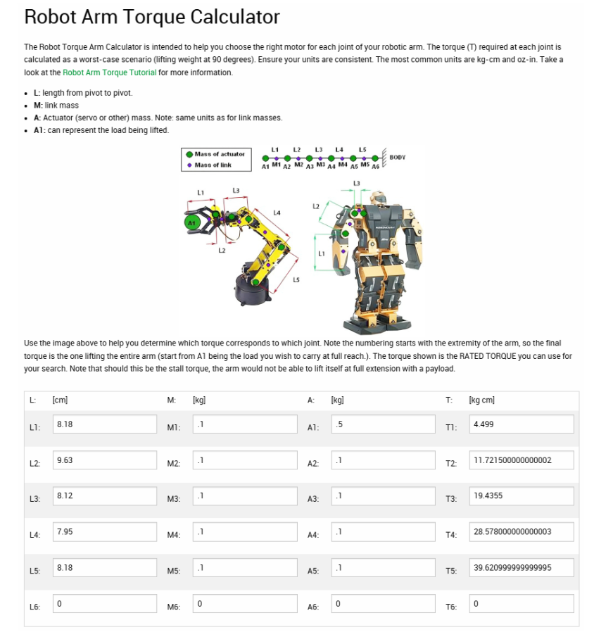
Here is an open source calculator to do the math for you. You can see that we need ~40 kg*cm of torque for a 1 lb claw + load given the weights and linkage lengths provided. This is what's used in your robot arm! Click "Robot Arm Torque Tutorial" for the math behind it!

╰┈➤ Go to Step 4: Controlling Said Motion

Mechanical engineers manipulate motion by changing how fast something moves, how strong it is, and which direction it goes, using parts like gears, levers, belts, springs, and motors.

For example, check out the claw of our arm. There is a spring attached from the main "palm" to each fingertip. This spring ensures that the fingers always return to it's pulled back/default starting position after you bend it by turning the individual finger servos with code.

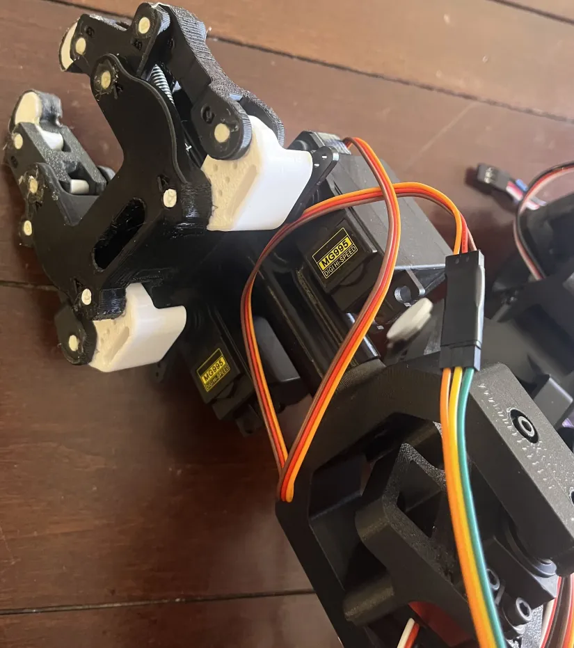
On a bicycle, your legs create motion, and gears manipulate that motion by changing how fast the wheels turn and how hard it is to pedal. Low gears make it easier to climb hills, and high gears make you go faster.

A car uses gears and brakes to control speed, direction, and stopping—this is manipulating motion. 

When you're trying to manipulate motion, think about how systems in the real world do it! For example, think about a bird. Birds change how their wings are shaped while flying. They spread feathers to slow down and pull them in to speed up or glide.

Engineering result:
Airplanes copied this idea using flaps and slats on their wings.

Motion being manipulated:

  • Speed

  • Lift

  • Direction

Why it matters:
Without flaps, planes couldn’t safely take off or land.

Find the T1 Servo 
Find the servo motor labeled 20 KG for the turret. 

Insert the T1 Servo into the Base Plate

Slide the T1 Servo into the Base Plate T1 bracket. The servo mounting holes should line up with the heat inserts previously inserted.

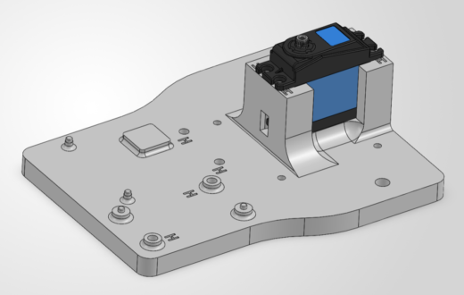
📌 Pro Tip: If you have a hard time sliding the servo into the housing, you may trim the black material on the edge of the servo.
Servo Trim Image

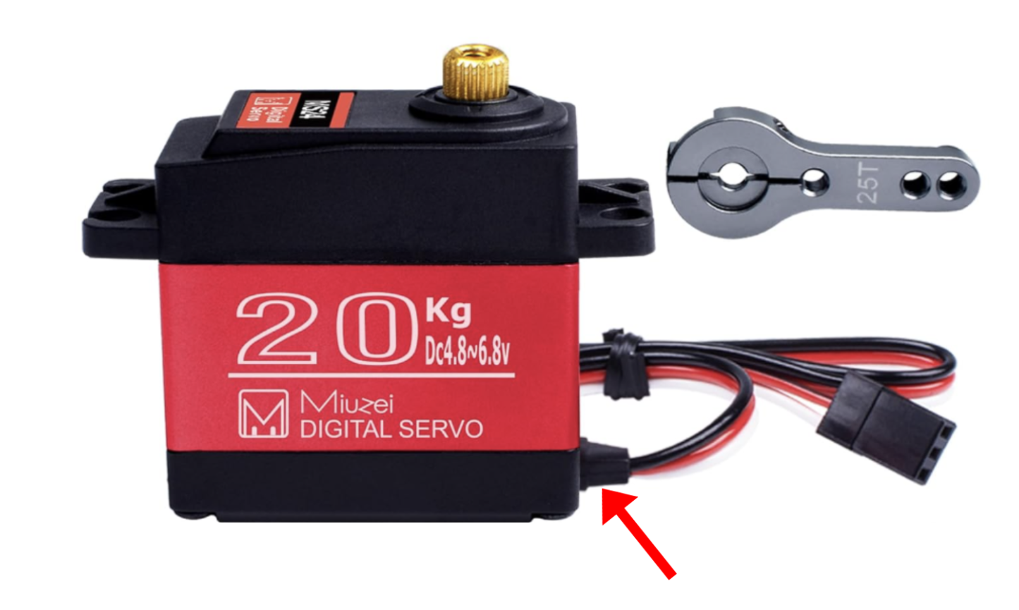
Warning: DO NOT CUT THE WIRES.


Attach the T1 Servo into the Base Plate

Screw in four M3 Washers and four M3 screws using the provided Allen Key to attach the servo to the base plate. Make sure there is a washer between the bolt head and the motor.

Warning: Double check the orientation of the motor. The pinion shaft of the motor needs to point towards the main base.

--
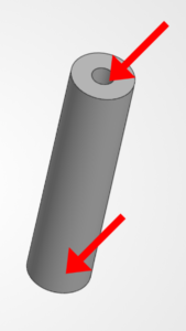
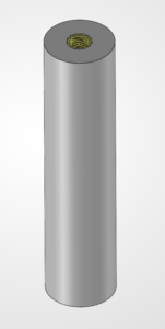
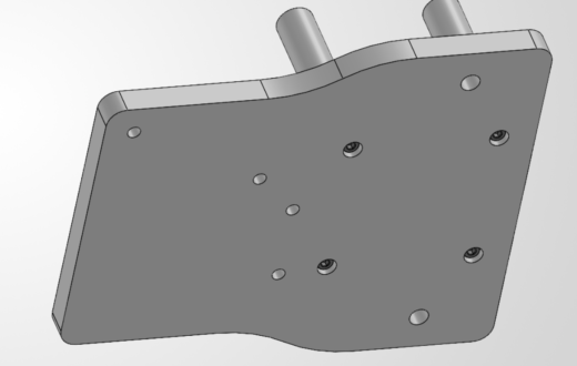
5. Attach the Standoffs to the Base

The standoffs separate two plates at a specific length and holds them together.

🛠️ Needed Parts: Base Plate (1x), Standoffs (4x), M3 Bolts (4x)

Attach the Standoffs to the Base Plate

Flip over the base plate and screw four M3 bolts into the holes on the bottom through the standoffs to fix them in place.

--
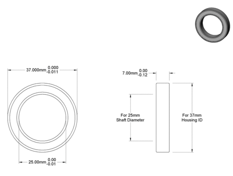
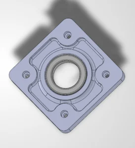
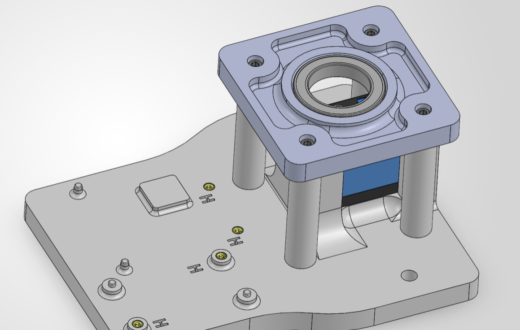
6. Attach the Large Bearing

The large bearing provides axis support for the entire arm when it spins on the lower turret.

🛠️ Needed Parts: Base Plate (1x), 6805-2RS Large Bearing (1x), Square Plate (1x)

📝 What is a bearing?
Bearings are small parts, but they do a huge job in machines. Their main purpose is to reduce friction (that rubbing that slows things down) and help moving parts spin smoothly without wearing out fast or falling off axis.

A skateboard is a perfect example. Inside each wheel are bearings that let the wheels spin freely and stay lined up. Without them, the wheels would grind, wobble, or slow down unevenly. Imagine trying to skateboard when one wheel spins fine and another barely moves...you wouldn’t get very far. ☠️ Almost everything that rotates on an axis needs a bearing.

Skateboard wheel bearing

Find the 6805-2RS Large Bearing

This is the only large bearing designated in the box. It is a steel sealed ball bearing that looks like this.

Slide the Bearing Into the Square Plate

Take the only large bearing and insert it into the slot as shown. This bearing acts as a lazy susan like guide for the turret. It should fit snugly into place.

💡 Try it! Hold your finger inside the bearing while holding the square plate still. Feel how the inside metal spins while the housing stays put!

--
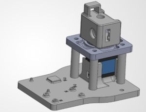
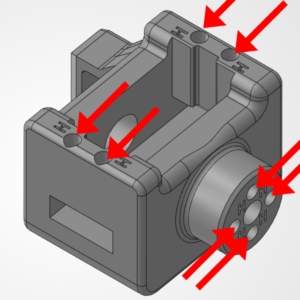
7. Attach the Square Housing

We need to attach the square housing to the standoffs now.

🛠️ Needed Parts: Base Plate (1x), Square Plate (1x), M3 Bolts (4x)

Attach the Square Plate to the Standoffs

Use 4x M3 Bolts to Screw the Square Plate to the Standoffs.

--
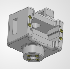
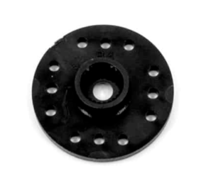
8. Attach the Servo Horn to the L1 Housing

The circular servo horn will eventually attach to our servo motor. But we need to attach it to the next joint of our arm first!

🛠️ Needed Parts: L1 Housing (1x), Circular Servo Horn (1x), M3 Bolts (4x)

Find the Circular Servo Horn
It’s a little circle with internal threads that will eventually attach to the servo!

Screw the Circular Servo Horn Onto the L1 Housing Block

Screw four M3 bolts through the bottom of the servo horn to attach it to the L1 Housing Block.

--
9. Set the Servo Start Position

This is a configuration step to make it easy to use the arm later. We are going to set the "middle" angle of each joint in the robotic arm to 90 degrees. This lets us use the entire range of motion for each joint if we move it left or right.

Setting Up Arduino IDE

🛠️ Needed Parts: Arduino Uno (1x), Arduino Cable (1x)

Follow the below steps to configure your software for the first time!


Navigate to this link to download the Arduino IDE software. This software is crucial to programming your robotic arm: 

https://www.arduino.cc/en/software/


Scroll down until you see this menu. Click the teal Download button on the right side. 


To install on:

  • Windows: Open the .exe, click Next until it’s installed. If it offers USB drivers or asks to run Java, say yes.
  • Mac: Open the .dmg, drag Arduino IDE into Applications.
  • Linux: Follow the download page instructions for your distro (or use your package manager if you know what that means).


Plug your Arduino into your computer's USB port using the included cable. It should light up!


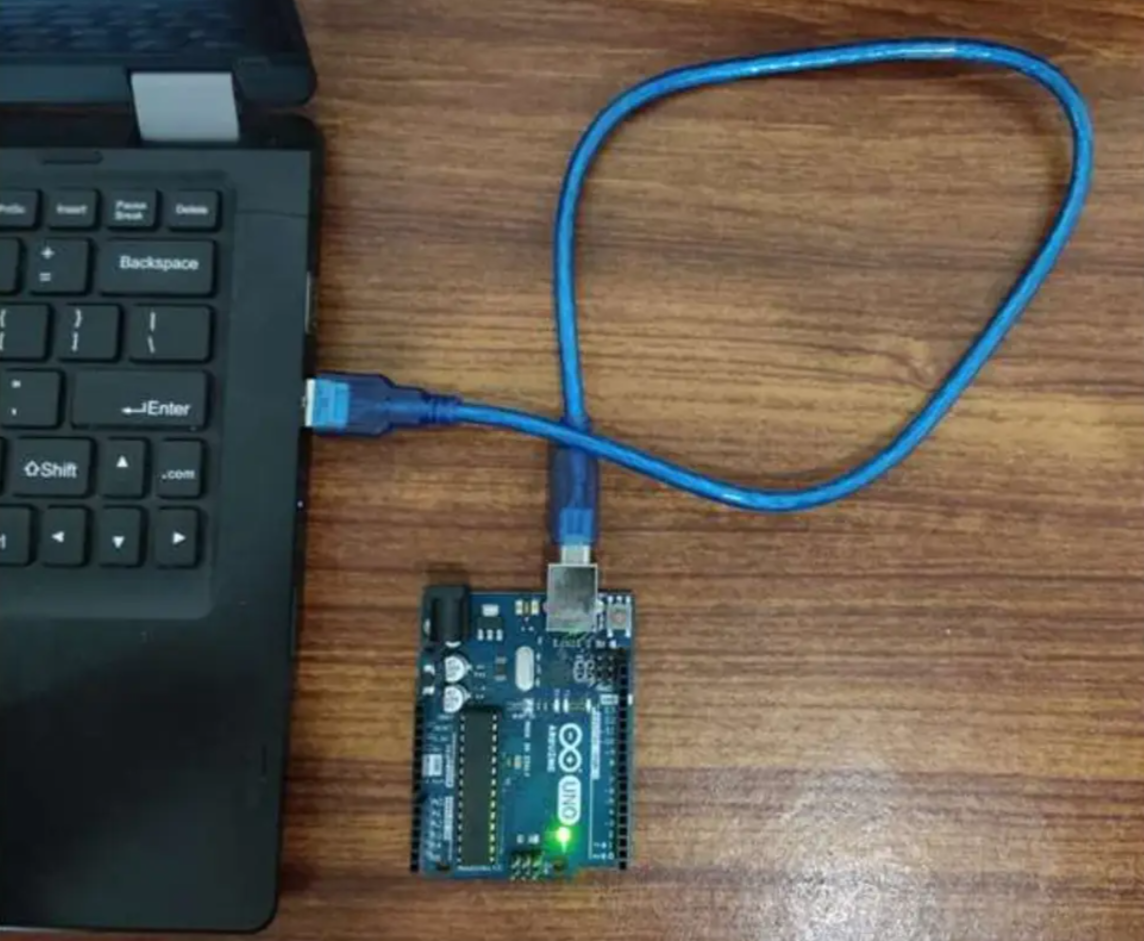
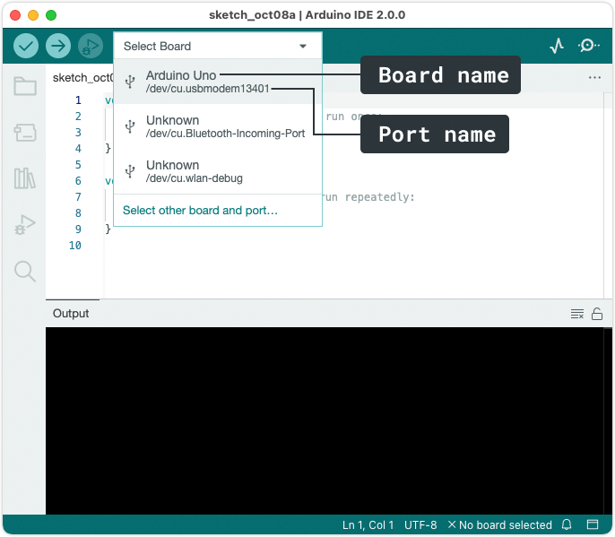
Select your board and port.

In Arduino IDE:

  • Find the board selector and click to open.

  • A list of ports will be displayed. If a board could be identified, the board name will be displayed, otherwise, it will display “Unknown”.

  • Tools → Board (pick Arduino UNO)
  • Then Tools → Port (pick the port that appeared when you plugged it in)


Yay! We can finally test it! 

Open: File → Examples → 01.Basics → Blink.


Click Upload. If the LED on the Arduino blinks, congrats...you are now legally allowed to say “hello world.”

Wiring the Test Servo Circuit

🛠️ Needed Parts: Arduino Uno (1x), Arduino Cable (1x), Test Cable (1x), Power Supply (1x), Power Supply Adapter Head (1x), Robot Arm Base (1x), Computer (1x)

Follow the below steps to wire your test bench!

Why set the servo position?

Servos don’t know where they are... they only know where you tell them to go. When a servo powers on, it will immediately move to its commanded angle. If parts are already attached and the servo isn’t centered, that first move can twist, slam, or snap something in your arm before you can even say "uh oh..."

Setting the servo to 90° puts it at its neutral, centered position. This gives your robot arm equal room to move in both directions, keeps joints aligned, and prevents accidental stress on gears, brackets, and wires.

We will be building the arm straight up with each joint set to 90°.

In short...
Center first. Build second. Break nothing (hopefully).

╰┈➤ Proceed to Section 2: Check Your Components.

Check your components.

You should have your Arduino, Arduino Cable, Test Cable, Power Supply, Power Supply Adapter Head, and Robot Arm Base all within easy reach. Your Arduino and Power Supply should both be unplugged at this time.

Before You Start: Make sure all power is OFF before connecting or adjusting any components. This step involves live electrical connections. Double-check wiring, move slowly, and keep hands clear when power is applied.

╰┈➤ Proceed to Section 3: Set The Power Supply.

Plug in the power supply.

When plugging in the power supply for the first time, you will need to set the voltage.

1. Plug in the power supply to a normal wall outlet.

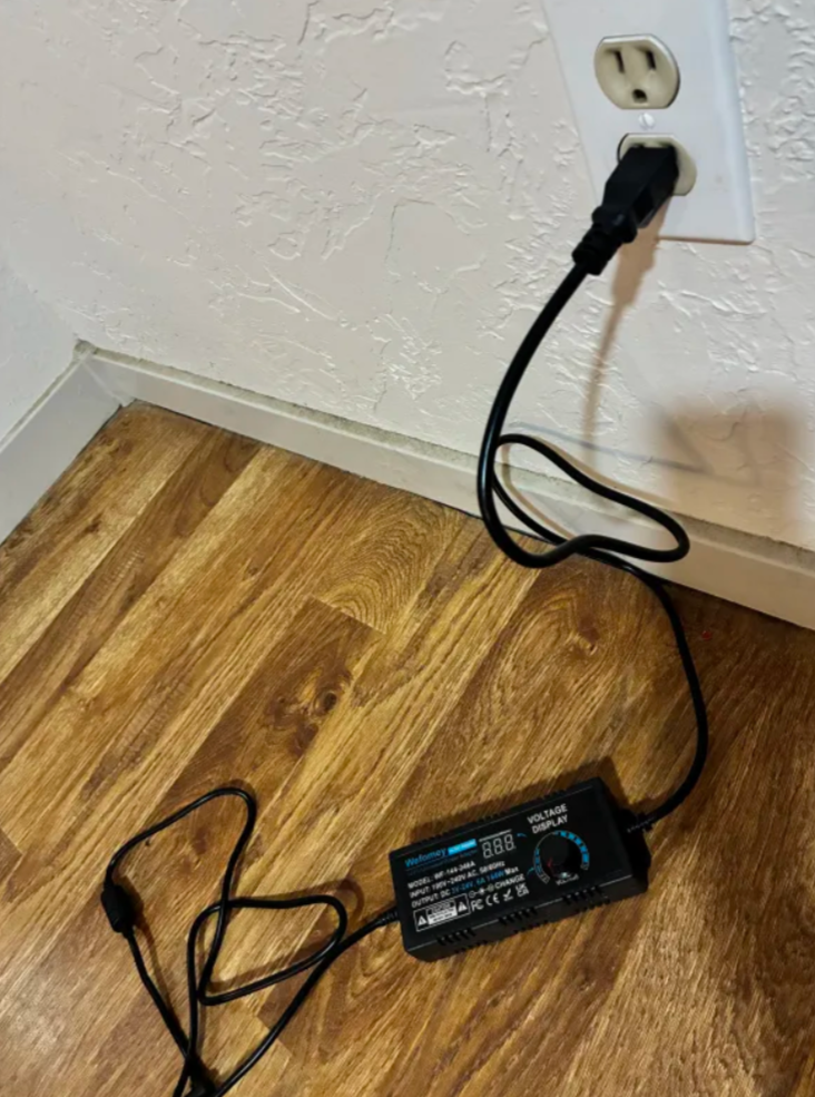
2. Turn the knob on the power supply until you hear a click. After a moment, the supply should come online. You will see the screen light up and show ~3.12V.

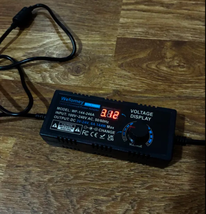
3. Slowly, slowly, begin turning the knob to increase the voltage. The servos in this kit run at 6V or less. You want to set the power supply to just under 6V. 

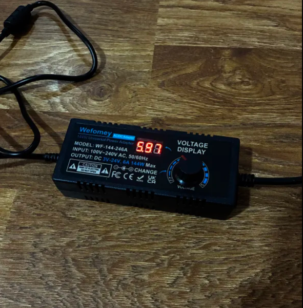
📌 Pro Tip: This is not an exact art! You want this number to be as close to 6V as you can, but if it's a little under (like mine at 5.97V), that is totally okay.

4. After the voltage is set, unplug the power supply from the wall & let it turn fully off. DO NOT TURN THE KNOB TO TURN IT OFF. The screen will go dark after several seconds.

Warning: The power supply voltage knob is very sensitive. Be careful bumping it when using the arm. Setting the voltage above 6V can cause serious damage to the components.

╰┈➤ Proceed to Section 4: About Servo Wires.

A little about servo wires.

Warning: The power supply and Arduino should both be off and unplugged before proceeding.

Every servo has three wires, and each one has a job.

Brown or Black = Ground

Red = Power

Orange / Yellow / White = Signal (PWM)

Wire Servo

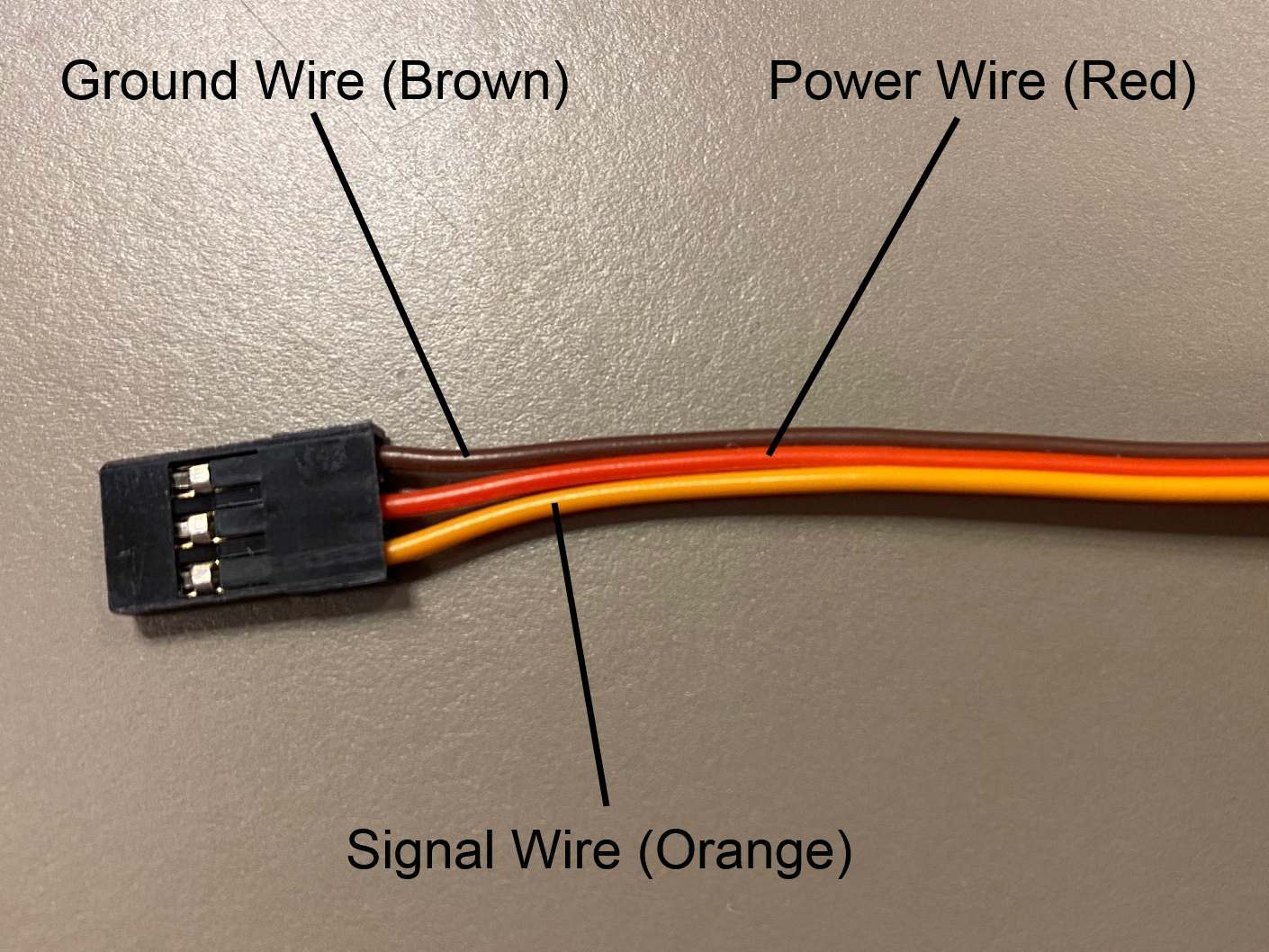
Let’s walk through what each one does and where it goes.

1. Servo Ground Wire (brown or black)

This servo wire will go to ground.

  • This goes into GND on the Arduino...
  • AND into ground on your 6V power supply.

Why both?

Because electronics need a shared reference point. Think of ground like “zero” on a ruler. If the Arduino and the servo don’t agree on where zero is, the signal makes no sense.

📌 Pro Tip: Your Test Cable has each wire already labeled.

2. Servo Power Wire (red)

This wire actually powers the motor inside the servo.

  • This will go into the 6V power supply's positive rail.
  • This should NOT be plugged into the 5V pin on the Arduino.

📝 Why? Servos pull a lot of current, especially when they start moving or hit resistance. Powering them directly from the Arduino can cause resets, glitches, or the Arduino quietly giving up on life.

3. Servo Signal Wire (yellow / orange / white)

This wire goes to any digital pin on the Arduino (for example, pin 9). This wire does not power anything. It just carries PWM instructions.

So what is PWM?

PWM stands for Pulse Width Modulation, which sounds scary but isn’t. PWM is just a way of sending information using time, not voltage.

Instead of changing how strong electricity is, we change how long it stays ON.

📝 What do you mean? Imagine a light switch. You flip a light:
ON → light
OFF → dark

Now imagine flipping it:
ON for a short time
OFF for a long time
ON again
OFF again

If you flip the light very fast, the light looks dim. If you keep it ON longer each cycle, it looks brighter. That idea of ON time vs OFF time...is PWM. The Arduino just does it way faster than we humans can process.

The Arduino basically sends the servo a repeating electrical pulse, about 50 times per second. The length of each pulse tells the servo what angle to move to. A short pulse says to move one way, a medium pulse says to go to the middle (90°), and a long pulse moves the other way.

Think of it like Morse code for motors.

╰┈➤ Proceed to Section 5: Wire The Test Bench.

Let's wire the test bench!

Alright! It's finally time to wire our test bench.

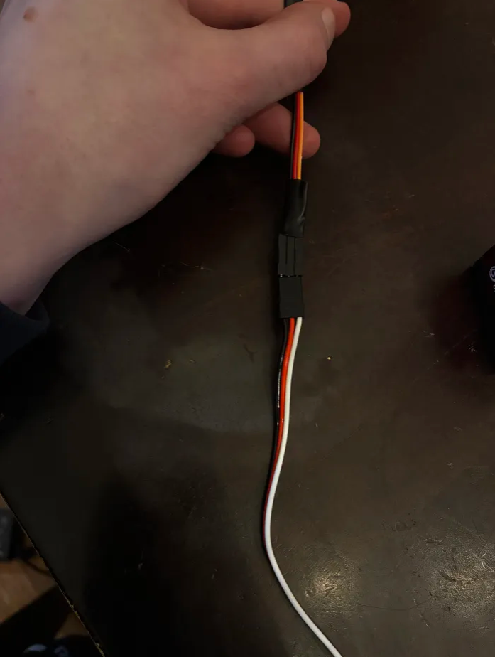
1. Connect the 3-wire side of your Test Cable to the T1 servo. The ground wire of your servo should connect to the black wire on the Test Cable. The power wire of your servo should connect to the red wire on the Test Cable. The signal wire on your servo should connect to the orange wire on the Test Cable.

2. On the 4-wire side of your Test Cable, locate the 6V wire and one of the 2 Ground Wires. Screw the 6V Wire into the Positive (+) side of the Power Supply Adapter Head. Screw the GND Wire into the Negative (-) side of the Power Supply Adapter Head.

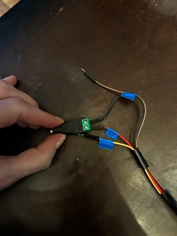
3. Plug the other GND wire into the GND pin of the Arduino. This is for that shared reference point we talked about in Section 4 - About Servo Wires

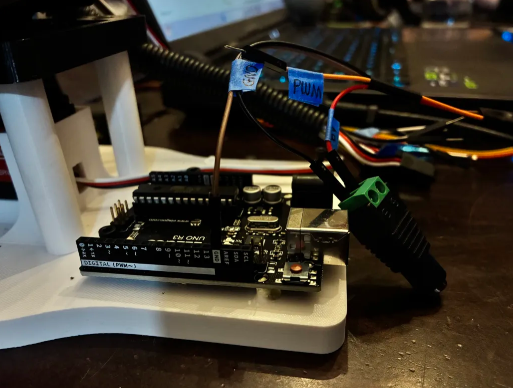
4. Plug the PWM wire into Pin 9 of the Arduino. You could use any digital pin on the Arduino for this, but the code following this will reference Pin 9.

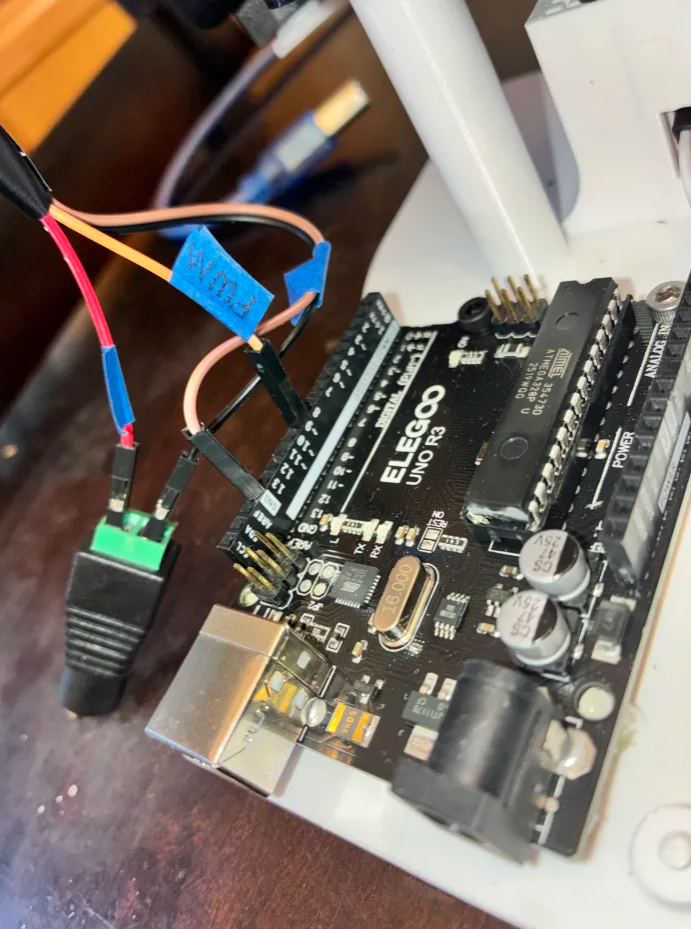
📌 Pro Tip: You could use any of the 13 digital Arduino Pins for this (and it would still work), but the code in this guide will reference Pin 9. 

5. All your wires should be plugged in now! Carefully plug the Power Supply output into the Power Supply Adapter Head.

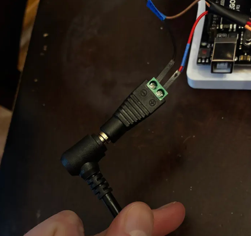
6. Plug your Arduino into your computer's USB port. 

7. Plug your Power Supply into the wall. It should kick on to the voltage you set earlier. 

Be careful! If you turn on the power supply and see that it has been bumped to a voltage above 6V, immediately turn the knob all the way down. Disconnect the Power Supply Adapter Head and repeat the steps in Section 4 - Set the Power Supply.

Plug in the Arduino (USB)

It's time to write our first code to set our servo position.

Create a New Arduino Sketch

Open Arduino IDE, and make a new sketch. To do this, click File → New. Delete anything in the code editor.

📝 Some notes before we start: Arduino code is written in C++. You don’t need to know all of C++ yet... you just need to know that Arduino uses it under the hood and hides some of the scary parts so you can focus on making things move.
Programming Meme


We’re going to build this program one piece at a time with explanations on how it works and what it does. This program will accept input into a terminal, then make the motor move to a specific position based on the input. If this doesn't make any sense yet, don't worry. It'll all make sense soon.

An Arduino program is built around two special functions:

setup() → runs once

loop() → runs forever

If you understand those two ideas, everything else clicks.

The Big Idea: How Arduino Code Runs

When the Arduino gets power, this happens in order:

The Arduino turns on.
setup() runs one single time.
loop() starts running.
When the code in loop() finishes, it immediately starts again.

This repeats forever, until power is removed from the Arduino.

Think of it like this.
setup() = morning routine.
loop() = your job for the rest of the day.

You don’t brush your teeth every minute. You do keep checking your phone all day.

Step 1: Include the Servo library

Type this at the top:

#include <Servo.h>

What this means:

In C++, #include pulls in pre-written code. The code library Servo.h contains all the timing logic needed to talk to a servo using PWM. It's like using a wheel. You don't need to reinvent it.

You’re basically saying:

"Hey Arduino, I want to use servo stuff."

Step 2: Create a Servo Object

On the next line, type:

Servo myServo;

What this does:

In C++, an object represents a real thing.

myServo is your software name for the physical servo plugged into the board. You could call it almost anything you want, as long as you use the same name everywhere. Nothing moves yet...you’re just giving the servo a name in code.

Step 3: Create Your Setup Function

Now type:

void setup() {

What setup() is really for:

setup() is where you put things that only need to happen once, like:
⬢ Starting communication
⬢ Connecting software to hardware pins
⬢ Setting safe starting positions to energize in

If you put something in setup(), Arduino will:
⬢ Do it once
⬢ Never touch it again unless reset (unplugged and plugged in again)

📝 Why is the function labeled void? Think of a function like a little helper robot.

You tell the robot:
“Hey, do this job for me.”

There are two kinds of helper robots.

Type 1: The “just do it” robot.
This robot does a job, but doesn’t hand you anything afterward.

Examples:
⬢ Turn on a motor
⬢ Move a servo
⬢ Set up hardware

These robots are labeled void. void means:
“I’ll do the job, but I’m not giving you an answer back.”

They do work, but return nothing.

Type 2: The “do it and tell me the answer” robot.
Some robots do thinking or math and then give you an answer.

For example:

Add Function

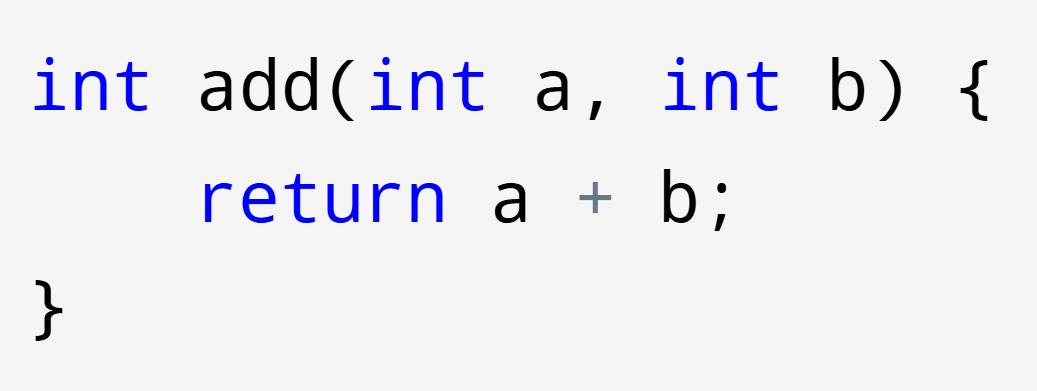
Here, int replaces void. int means:
“This robot gives back a number. It returns a value.”

The line: return a + b; is the robot saying: “Here’s the answer.”

You can store that answer and use it later:

Add Function Result

This gives you the number 7.

But in setup(), we’re not asking for answers. We’re just telling the robot to set things up. So we use void for now.

Step 4: Start Serial Communication.

Inside setup(), type:

Serial.begin(9600);

What this means:

This opens a communication channel between your computer and the Arduino.

Serial = the USB connection.

9600 = the speed (baud rate)

This lets us send commands like A, B, and C from the Serial Monitor. The Serial Monitor is basically a window (also called a terminal) you can type text into or view text from the program itself.

Step 5: Attach the Servo to a Physical Pin

Still inside setup(), type:

myServo.attach(9);

What this means:

This tells Arduino which digital pin is sending the PWM signal. Remember how we connected our servo's signal wire to Pin 9?

Step 6: Center the Servo

Still inside setup(), type:

myServo.write(90);

What this means:

This tells the servo to go to 90 degrees.

Step 7: Close setup()

Type:

}

Your code should now look like this:

#include <Servo.h>
Servo myServo;
      
void setup(){      
      Serial.begin(9600);
      myServo.attach(9);
      myServo.write(90);
}      

At this point, running this code will set the servo to the 90 degree position.

📌 Pro Tip: Don't forget your semicolons when you're coding!
Programming Memes

Step 8: Create Your loop() Function

Outside of setup(), type:

void loop(){      

What this means:

loop() is for things you want to keep checking or reacting to, like:

“Did someone press a button?”
“Did data arrive over Serial?”
“Did a sensor value change?”

Arduino runs loop() thousands of times per second. We're going to use it to take in a message from our terminal. We can use that message to control our actual servo.

📝 Think of an XBOX controller. When you move a knob or click a button on a game controller, you're sending a message to a microcontroller (the Arduino). This message gets interpreted by the code, and is used to control the screen! That's what we're building, but using letters instead of a physical game controller.

Step 9: Only React When Input Arrives

To do this, we are going to use something called an IF statement. Think about when your mother says something like... "IF you eat your dinner, you can have dessert."

An IF statement does that, but in code. In C++, that looks like (don't copy/paste this in):

if (you eat your dinner) {
      you can have dessert;
}

Anything inside the parentheses () is the condition.

Anything inside the curly braces {} is what happens if the condition is true.

No dinner? No dessert.
Condition not met? Code doesn’t run.

So we're going to use an IF statement to check if we've received a message. Do you remember when we typed Serial.begin(9600); to start a Serial text terminal earlier? We told the Arduino, "hey, you're going to talk to a computer now."

Now we're going to use a Serial command in C++ to check for a message. C++ has a function called: Serial.available() that does one thing. It asks your computer a yes-or-no question.

“Has the computer sent me any data yet?”

If no → it returns 0 (false).

If yes → it returns 1 (true).

That makes it perfect for an IF statement.

Let's put it together.

if (Serial.available()) {

What this means: This is saying, in human terms:

IF the computer terminal has sent me LITERALLY ANYTHING, do everything in the curly braces. Otherwise, skip this entire section.

📝 Why do we need this check? Arduino runs loop() over and over again, very fast. If we didn’t check first, the Arduino would try to read data that doesn’t exist... and get confused.

So this line protects us by saying:

"Don’t do anything unless there’s actually something to read."

Step 10: Reading the Message (One Letter at a Time)

Now that we’ve checked IF a message exists, we need to actually read it. Computers don’t read words the way humans do. They read one character at a time.

That means if you type:

G

The Arduino sees a single character... not a word, not a sentence.

So let’s read a character from the terminal.

Type this line inside the IF statement:

char cmd = Serial.read();

📝 What is char? In C++, every piece of data has a type.

int → whole numbers

float → numbers with decimals

char → a single character

string → multiple characters grouped together (text)

Examples of char values:

'A'
'b'
'9'


Important: '9' is not the number nine.

9 (no quotes) → the number nine → an int
'9' (single quotes) → the character “9” → a char

Even though '9' looks like a number, the computer treats it as a symbol, not something you can do math with.

Notice the single quotes. That’s how C++ knows this is exactly one character, not a number and not a word.

So what does this line of code actually do? It creates a new char called cmd. The word cmd is a variable we can use to describe whatever we read from the Serial monitor. Whenever we want to reference the text we got from the Serial monitor, we'll use the word cmd.

📝 What is the difference between a char and a string? A char and a string are not the same thing, even if they look similar.

A char:
– Holds exactly one character
– Uses single quotes ' '

Examples:

'A'
'?'
'9'

A string:
– Holds multiple characters
– Uses double quotes " "
– Can be a word, sentence, or even just one letter

Examples:

"A"
"servo"
"Move to 90 degrees"

Important: Even "A" is still a string, not a char.

This matters because computers care about exact data types. A char uses 1 byte of memory, while a string uses many bytes and behaves differently in code.

Quick rule to remember:
'A' → one character → char
"A" → text → string

Step 11: Making Decisions with switch()

Now that we know what letter was sent, we need to decide what to DO with it. We want to spin a motor to different positions when we receive a command through the Serial Monitor, remember?

We could use a bunch of IF statements…

if (cmd == 'A' || cmd == 'a') {     
      myServo.write(0);
}      
else if (cmd == 'B' || cmd == 'b') { myServo.write(90); }
else if (cmd == 'C' || cmd == 'c') { myServo.write(180); }
else if (cmd == 'D' || cmd == 'd') { myServo.write(270); }
.
.
.

…This works. So why don't we love it?

Coding like that gets loooooong fast. The longer your code, the slower it gets. When we're working with real motors, we want our code to be as fast as possible!

Imagine you turn on a game controller and press a button on it. Then the controller says: "Okay! I'm on! I’ll check if you pressed the red button…

No?

Okay, I’ll check if you pressed the blue button…

No?

Okay, I’ll check if you pressed the green button…

No?

(…keeps checking every button, one by one…)

That controller is using a bunch of if statements. Now imagine a different game controller.

You press a button, and it says:

"You pressed the green button. I know exactly what to do."

That controller is using something called a switch.

We already read one character from the computer and stored it here:

char cmd = Serial.read();

Now we’re going to look at that character and choose an action.

In C++, a switch looks like this:

switch (cmd) {

This line is saying:

"Look at cmd, and compare it against a list of possible values."

Inside the switch, we define those possibilities using case.

switch (cmd) {     
      case 'A':

Step 12: Move the Servo to 0° - Our First Command

Let’s add our first command.

switch (cmd) {     
      case 'A':     
      case 'a':     
            myServo.write(0);     
            Serial.println("Servo --> 0 degrees");     
            break;

Here’s what’s happening, step by step:

case 'A' checks for a capital A
case 'a' checks for a lowercase a

If either one matches, the code below runs.

myServo.write(0); → tells the servo to move to 0 degrees.

Serial.println(...) → sends a message (a string!) back to your computer so you know it completed the instructions.

break; → VERY important. It tells the Arduino: "Stop here. Don’t check any more cases. You did it!"

Step 13: Case 'B', Case 'C'...

Now we repeat the same pattern.

      case 'B':     
      case 'b':     
            myServo.write(90);     
            Serial.println("Servo --> 90 degrees");     
            break;

Same structure. Different angle.

This consistency is on purpose. Once you understand one case, you understand them all.

      case 'C':     
      case 'c':     
            myServo.write(180);     
            Serial.println("Servo --> 180 degrees");     
            break;

But what if I mistype?

What if I type... 'Q'? Or 'J'? Orrr.. "gummy bears"? (I know you're thinking about them.)

That's why we need...

Step 14: The default Case... When Someone Types the Wrong Thing

What DO we do if someone types the wrong key?

Instead of doing nothing and confusing them or breaking, we handle it.

default:     
      Serial.println("Unknown command");     
      break;

Step 15: The Often Forgotten

The last step is always to close our loops! We need to close out our Switch, IF, and Loop functions.

At the end of our code, we close everything we opened:

            }     
      }     
}

Each closing brace matches something earlier:

• One closes the switch
• One closes the if
• One closes the loop()

Braces matter. A lot.

The Final Mental Roadmap

Here’s what your Arduino is doing now, in plain English:

• The Arduino powers on
setup() runs once
– Starts talking to the computer
– Connects the servo to a pin
– Centers the servo safely

loop() runs over and over forever
– Checks: "Did the computer send anything?"
– If yes, reads ONE character
– Uses a switch to decide what that character means
– Moves the servo exactly once

Nothing moves unless you tell it to.

One letter in. One clear decision. One motor action.

And you've just written your first servo test code! Here it is, all together. 🙂

#include <Servo.h> 
Servo myServo;
      
void setup(){      
      Serial.begin(9600);
      myServo.attach(9);
      myServo.write(90);
}      


void loop(){      
  if (Serial.available()) {
    char cmd = Serial.read();
    switch (cmd) {     
      case 'A':     
      case 'a':     
            myServo.write(0);     
            Serial.println("Servo --> 0 degrees");     
            break;
      case 'B':     
      case 'b':     
            myServo.write(90);     
            Serial.println("Servo --> 90 degrees");     
            break;
      case 'C':     
      case 'c':     
            myServo.write(180);     
            Serial.println("Servo --> 180 degrees");     
            break;     
      default:     
            Serial.println("Unknown command");     
            break;
            }     
      }
}

Step 16: Play with it!

You’ve written the code. Now let’s make our motor do something.

1️⃣ Plug in the Arduino Use a USB cable to connect the Arduino to your computer.

If this is your first time plugging it in, give your computer a few seconds to recognize it.

2️⃣ Select the Board and Port In the Arduino IDE:

Go to Tools → Board
Select the Arduino you’re using (Uno)

Then go to Tools → Port
Select the port that appeared when you plugged in the Arduino.

(If you’re not sure which one it is, unplug the Arduino and plug it back in. The port that appears is the correct one.)

3️⃣ Upload the Code Click the Upload button (the arrow at the top of the Arduino IDE).

You’ll see a message that says:

“Done uploading.”

That means the code is now living on the Arduino’s brain. The servo should move to 90°.

That’s your sign that: the wiring is correct the code is running the robot is alive

5️⃣ Open the Serial Monitor In the Arduino IDE:

Go to Tools → Serial Monitor

Set the baud rate (bottom right) to:

9600

And set line ending to:

No line ending

6️⃣ Send Commands

Click in the text box and type:

A → Hit enter, and your servo will go to 0°.
B → Your servo will go to 90°!
.
.
.
and so on!

If the servo moves when you type letters, you did it!

You just uploaded real C++ code, talked to a microcontroller, and controlled a motor.

Now you get to play with it and watch your motor spiiiin! If you have trouble viewing the entire video, put it into picture and picture to see it from top to bottom.

Step 17: Set Your Motor Back to 90 Degrees

When you're done, make sure you set your motor to 90 degrees again.

IMPORTANT: DO NOT FORGET TO SET THE SERVO TO 90 DEGREES BEFORE MOVING ON.

--
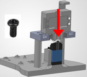
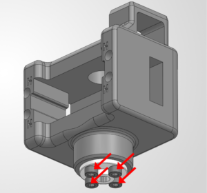
10. Place the L1 Housing

With the servo still energized, we're going to attach the L1 Housing Block!

🛠️ Needed Parts: L1 Housing (1x), Base Plate (1x), Pinion Screw (1x)

Attach the L1 Housing to the Servo

Warning: THE SERVO MUST STILL BE PLUGGED IN TO YOUR ARDUINO AND SET TO 90 DEGREES FOR THIS STEP.

Slide the Servo Horn on the L1 Housing Block onto the servo. The servo horn has internal threads that will lock onto the servo. It should press fit into place.

You want to place it so that the wire through-hole is facing the left side of the base plate, exactly like the image below. You want the L1 Housing Block to be attached as straight as possible.

Attach the L1 Housing Block to the Servo

Screw in the M3 Phillips Screw through the top. This is used to hold the servo motor and servo horn together. Take a Phillips screw driver, and using the top hole, install it onto the shaft of the motor pinion.

Warning: PLEASE DONT FORGET THIS STEP, OR YOUR ROBOT WILL FALL APART.

--
11. Time to divide the assets.

1. If you are completing this project alone, carefully and quietly open the bag of squishy bears.

Warning: High level of noise might attract nearby predators!

2. If you are completing this project in a group, divide the bears as a team or assign a bearganizor to split the gummies.

Warning: Watch the bearganizor closely, if a bear goes missing, proceed to a tribal council to vote on punishment for bearnapping and illegal consumption without tribal/ assembly guide authorization.

3. You will divide the bears over six chapters. Spread the entire contents of the bag on a clean plate and arrange them according to the picture. The color doesn't matter. The total number in your package may vary slightly.

You may now enjoy ONE PILE of roughly 15 or so bears. If there are extras, tribe may vote on the highest performing constituent from each chapter to have the extra offering. If you're alone... we are not liable for any sugar rush incidents.

You're all set! On to Chapter 3: L1-L3 Assembly! ᯓ✈︎