Chapter 8: Remote Controller Project

--
1. Intro into Mechanical Design.


Rule of Thumb: CAD represents perfection, we do not live in a perfect world. So, how can we use mechanical engineering to control perfect as much as possible?

--
2. Design Tips/ Thoughts to Have Starter Pack.

Things will be made and assembled by humans, always think of if it’s possible to manufacture, and how? Can I even assemble this? What fasteners to use, where? How?

Design with the expectation of 80-90% efficiency, never 100% so add safety factors.

Tolerances are key, try to keep things within +/- .005 inch which is the avg thickness of human hair.

When 3D Printing, or where heat is applied, OD (Shaft) grows & ID (holes) shrinks, so make sure to add +/- .005in to .01in depending.

Fillets are free, add them everywhere it’s a safety and aesthetics thing.

NO FLOATING SKETCHES OR PARTS! Always fully define your sketches and assemblies in CAD. Don't just toss things together, dimension them, label them properly.

Use construction and centerlines a lot, they can help you speed up, and make things a lot easier, especially to mirror your sketches.

Parts are made from a single stock of material if traditionally manufactured, think of how it will be made. Watch videos as needed on CNC Machining.

When mating in an assemblies, try to stick with faces only, no vertices, or edges.

We use all M3 hex cap head bolts in the arm design, it helps standardize our parts inventory, reduce costs, assembly headaches etc. If you can, standardize!

4. Organization

This is an example of a file naming convention. You can use this, or make your own, point is to be organized. Don't name a file "blue spinny part" and move on.

4. Free online CAD files

You do not need to reinvent the wheel.

People share free CAD parts you can download and drop straight into your assemblies—like a servo as a STEP file instead of wasting time and modeling it yourself. McMaster-Carr also has free CAD (great for bearings). This will be your best friend: don’t model COTS (Commercial Off The Shelf) parts from scratch, just verify dimensions with vendor drawings.

GrabCAD: [https://grabcad.com/library](https://grabcad.com/library)

McMaster-Carr: [https://www.mcmaster.com/](https://www.mcmaster.com/)

5. Plan your design with a layout sketch!

Plan for success! If you are building a toy car, think of as many components it needs as you can, where they go, and what they might do. For example, you need wheels...bearings for supporting the wheels...a body frame...what else?

You can take your idea and draw out a rough layout sketch of what you think the design could look like. If you suck at drawing like I do haha, you can make a 2D layout sketch on a CAD software. I do recommend paper and pencil.

Here is a random ball launcher I made once. Note the layout and how it relates to the 3D model.

The more detailed you can be now, the more heartache you save yourself down the line. Juuuust don't spend too much time doing this. Sometimes...you just need to dive in head first, try, fail, try again and so on.

--
6. Installing Fusion360

Fusion 360 is a free for private use 3D Computer Aided Design (CAD) program anyone can use to create and test models of parts and assemblies. It’s commonly used in engineering and robotics classes to turn ideas into real, buildable designs.


Navigate to this link to download the Fusion360 software. This software will allow you to design custom parts or assemblies for all of your wildest creator dreams.

https://www.autodesk.com/products/fusion-360/personal?us_oa=dotcom-us&us_at=Fusion%20free%20personal%20use&us_si=10e46eae-d103-491c-b0f6-35cc8d944eb8https://www.arduino.cc/en/software/


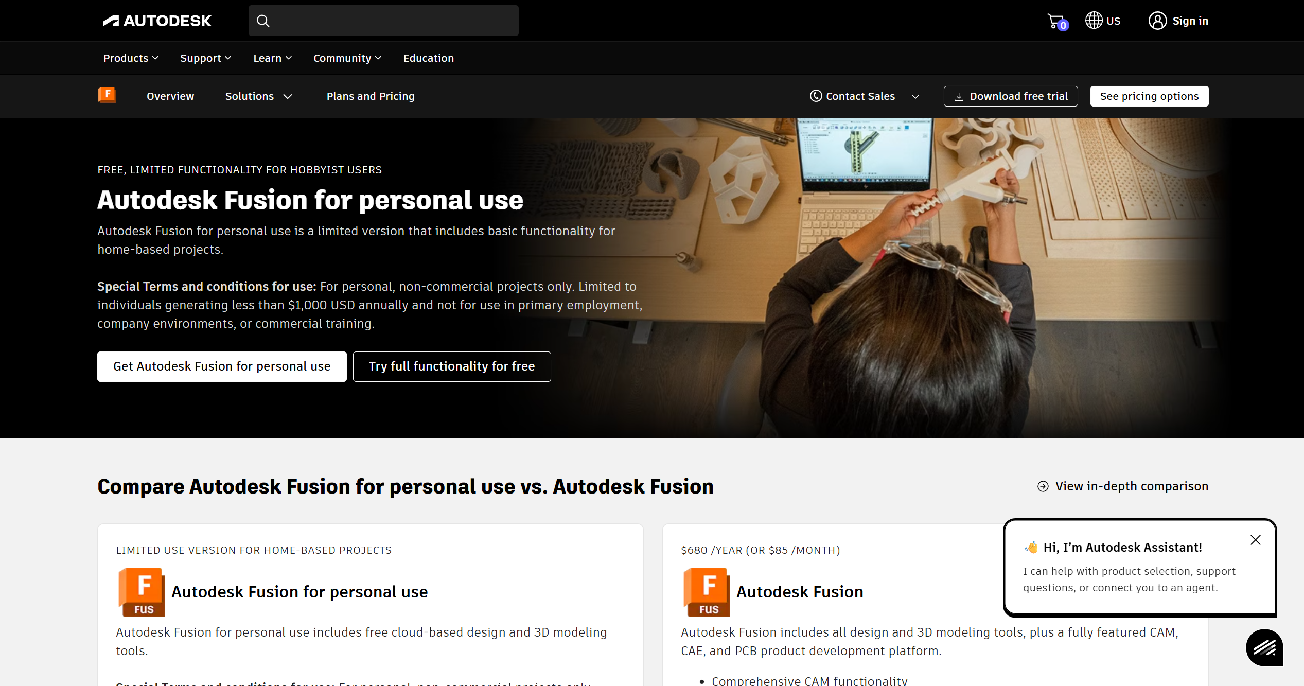
Scroll down until you see this menu. Click the white "Get Autodesk Fusion for personal use" button on the left side. 


Create a free account with Autodesk using your PERSONAL email (ex: johndoe@gmail.com).

Please please do yourself a favor, do not use a mac for CAD from now to the end of time. Windows only! Mac for CAD is like I tell you to go build a house with high heels on. Possible? Yes... but Pablo will judge you.


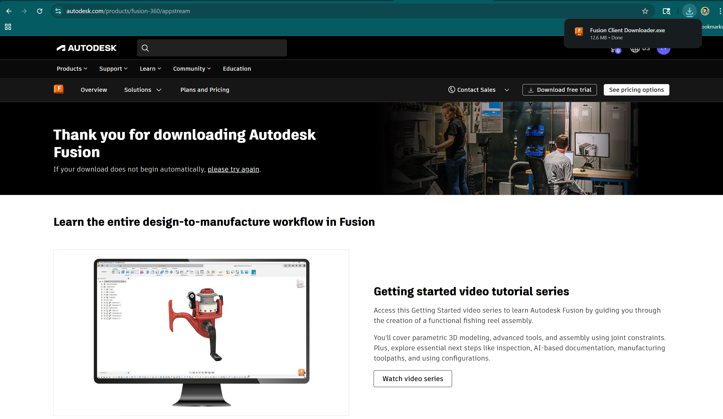
Once you create an account with them, you will immediately get a download link for free. Continue and install.


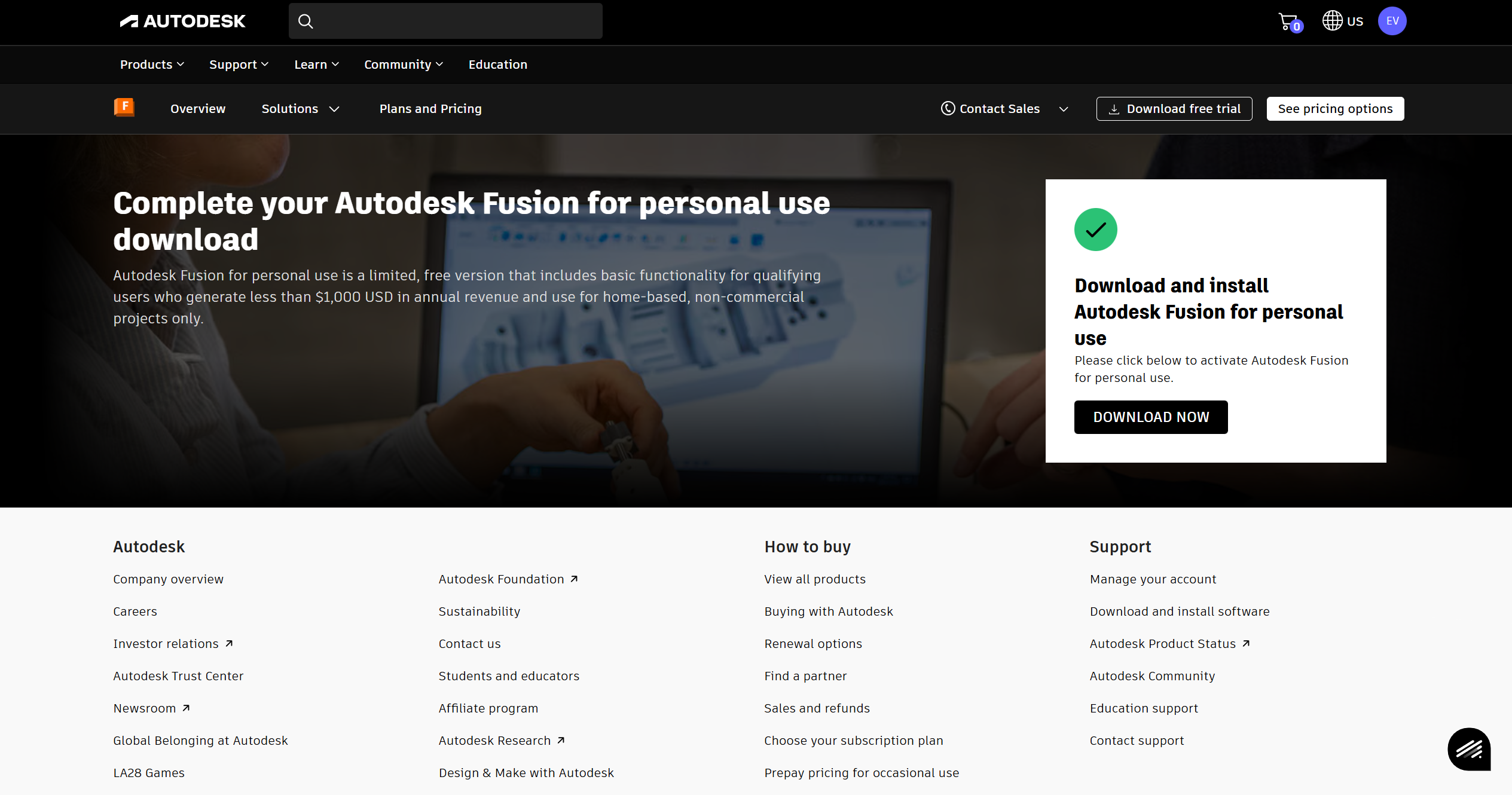
When it's done downloading, it'll pop up in the top right corner, if not go find it wherever you downloaded it to in your file explorer.

Click the "Fusion Client Download.exe" file.


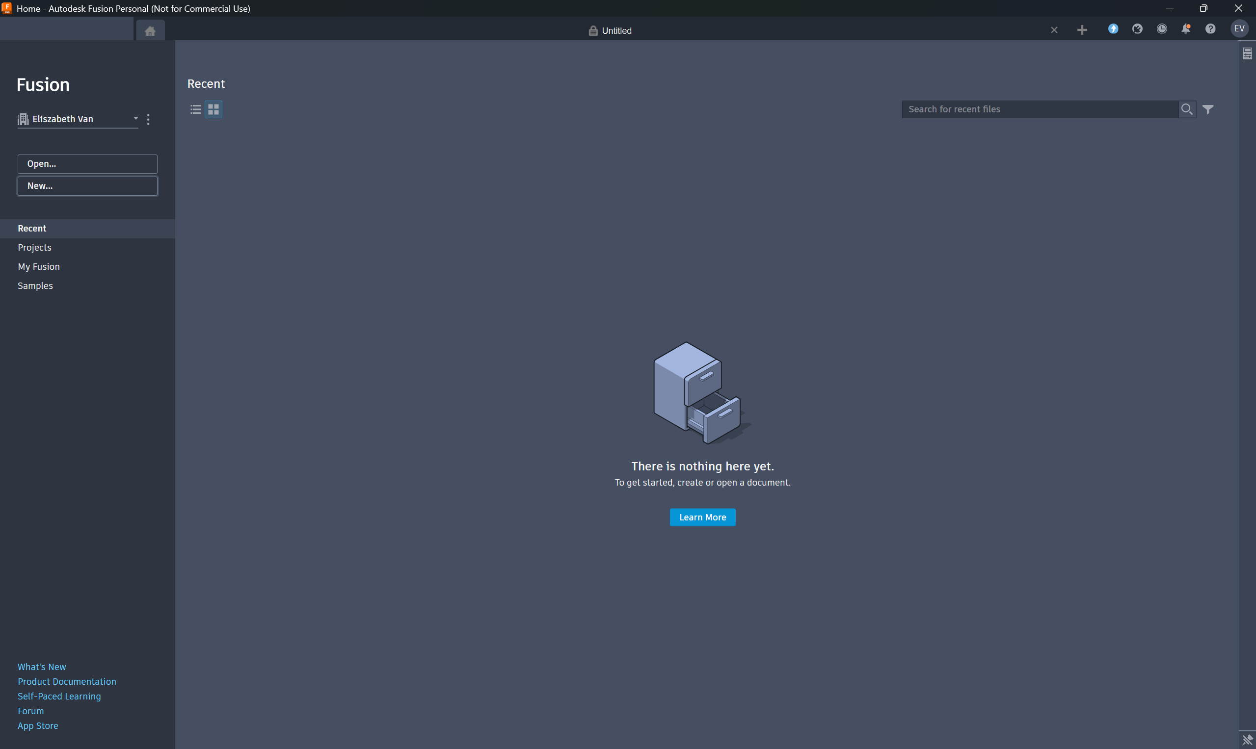
It takes a minute to install. When done, sign into your account!

--
7. Let's Make Something and Practice CAD!

Fusion 360 is a free for private use 3D Computer Aided Design (CAD) program anyone can use to create and test models of parts and assemblies. It’s commonly used in engineering and robotics classes to turn ideas into real, buildable designs.

Let's make something!
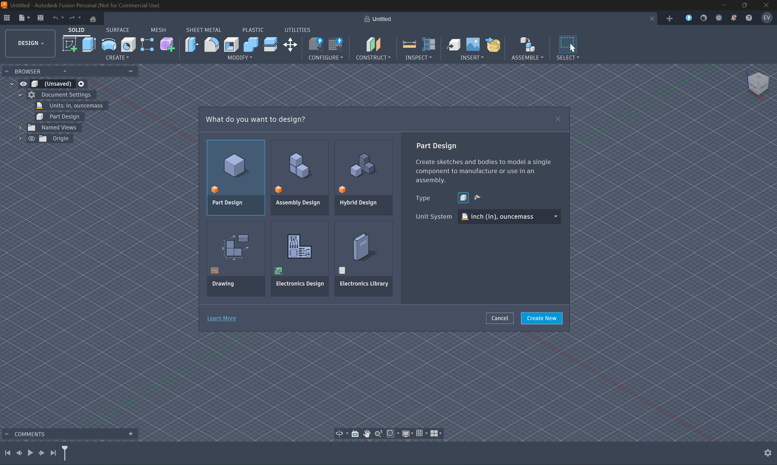
  1. Click New.

  2. Select Part Design then click Create New.

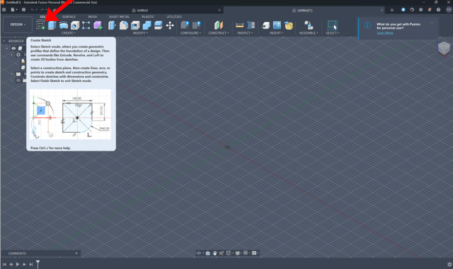
  3. Click create sketch and chose a plane to sketch on. For now just click the front plane, doesn't matter too much though! This is where we draw our 2D sketches to later turn into 3D objects.

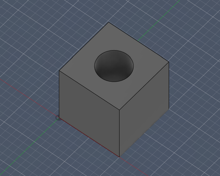
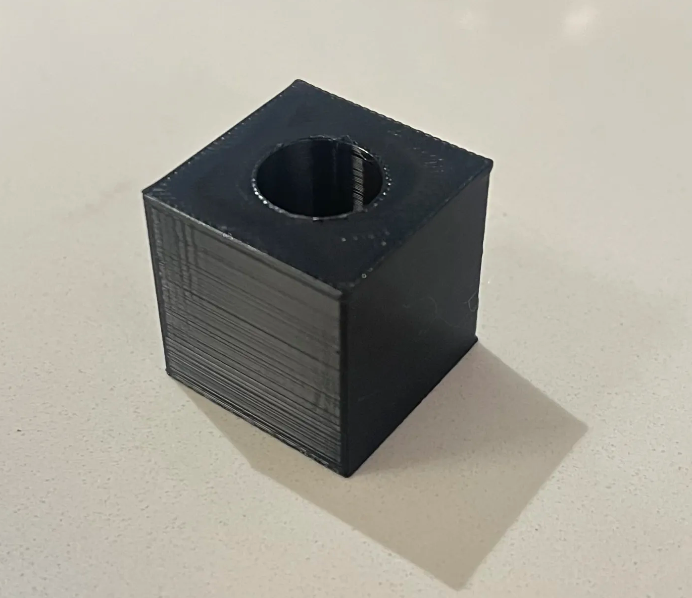
  4. We are goin to make a 1x1x1 cube and manufacture it in real life on a 3D printer. In the sketch section, click that 2nd rectangular sketch tool. Click from the origin, then drag out (anywhere) to create a 2D box sketch. Then Click D on your laptop to activate the dimensioning tool. Click the edges and set them to 1 each. You only need to do two sides.

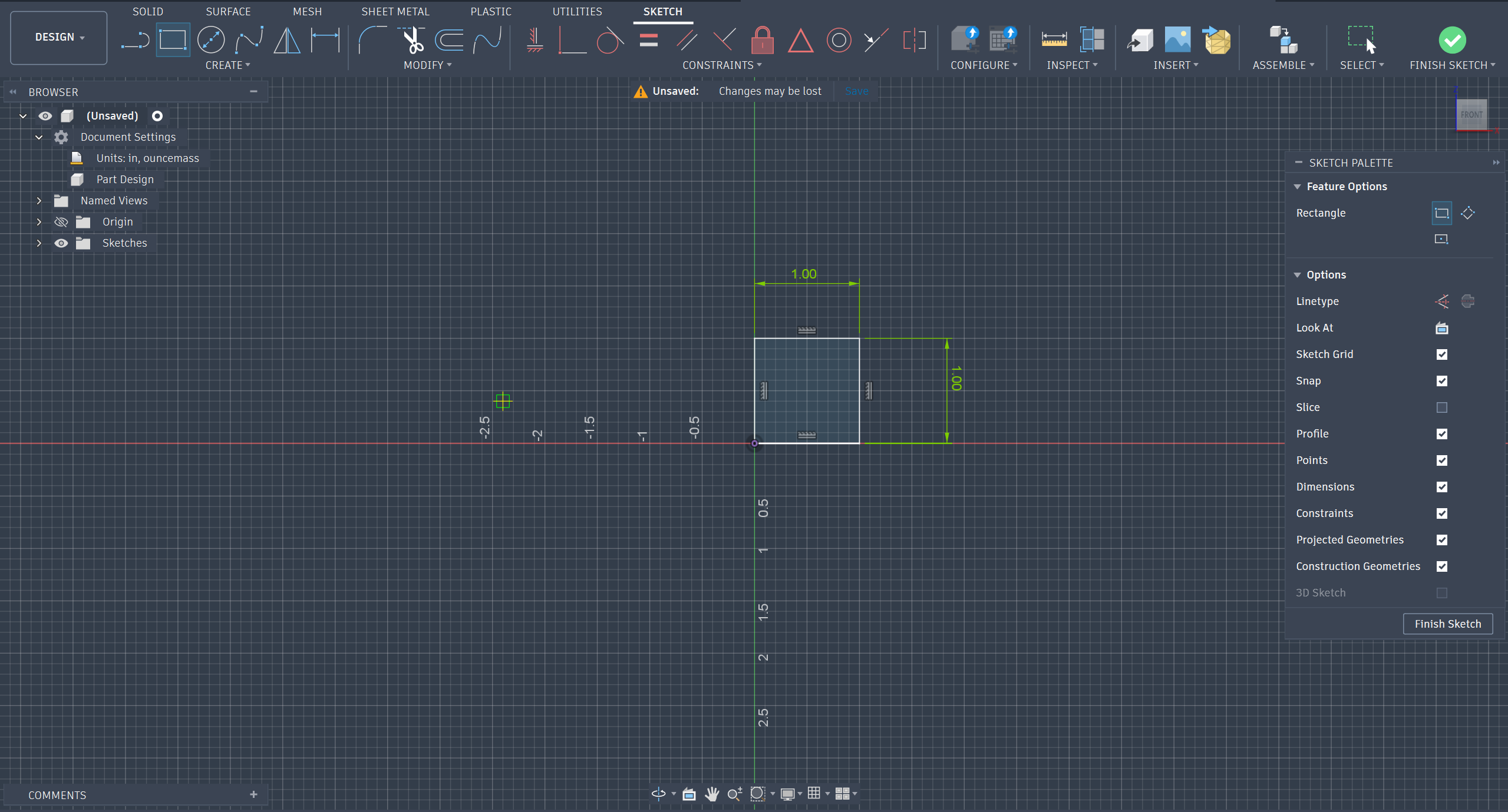
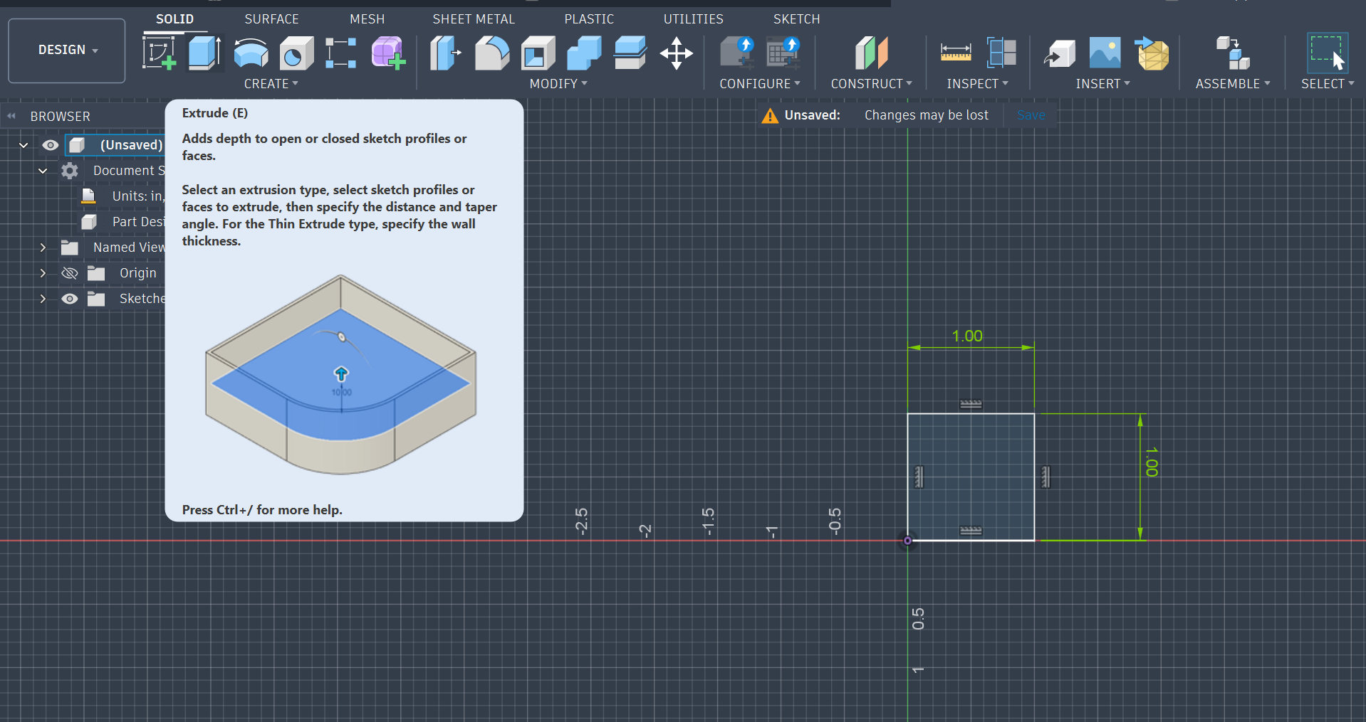
  5. Now go to the solids section, and click extrude. Type in the value 1.

    Yay you made a cubeeee!

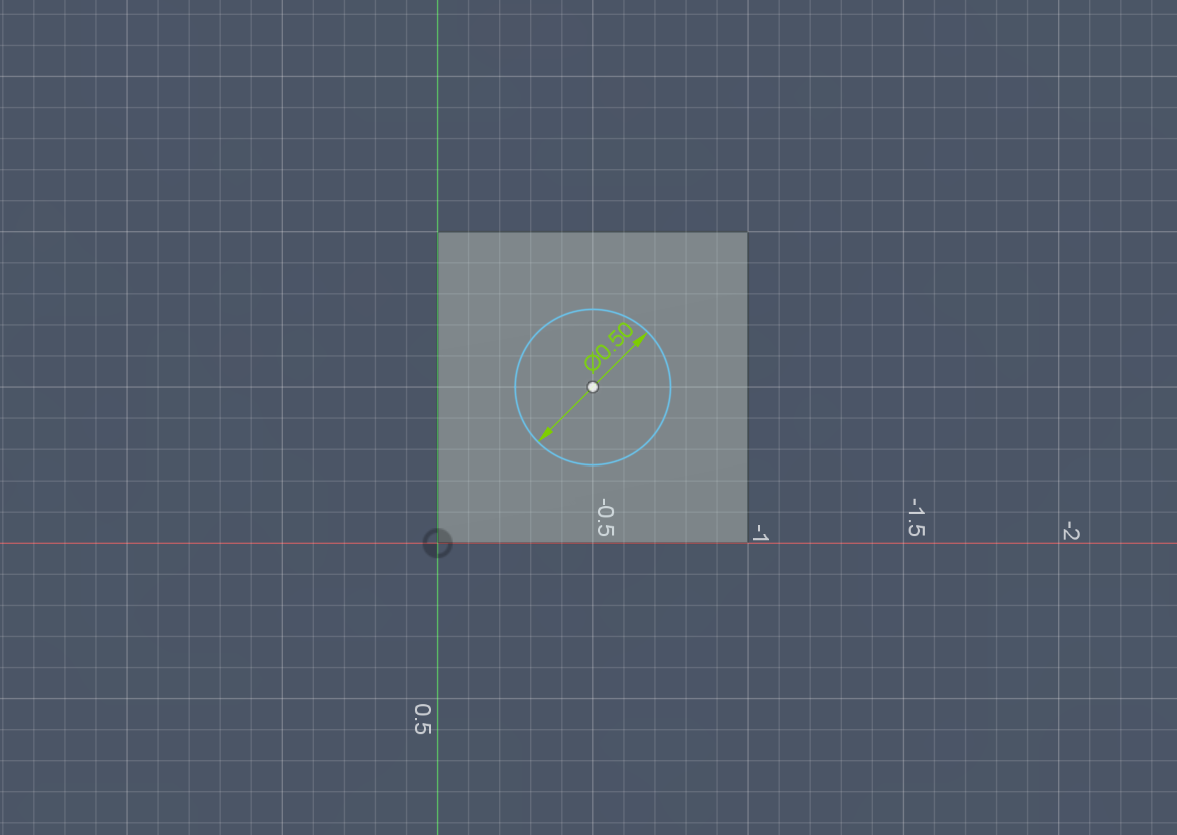
  6. Now put a hole in it. Click a face, any face and click create sketch in the top left hand corner. Select the 3rd circle option, and draw a circle in the center of the part. Make it 0.5in diameter.


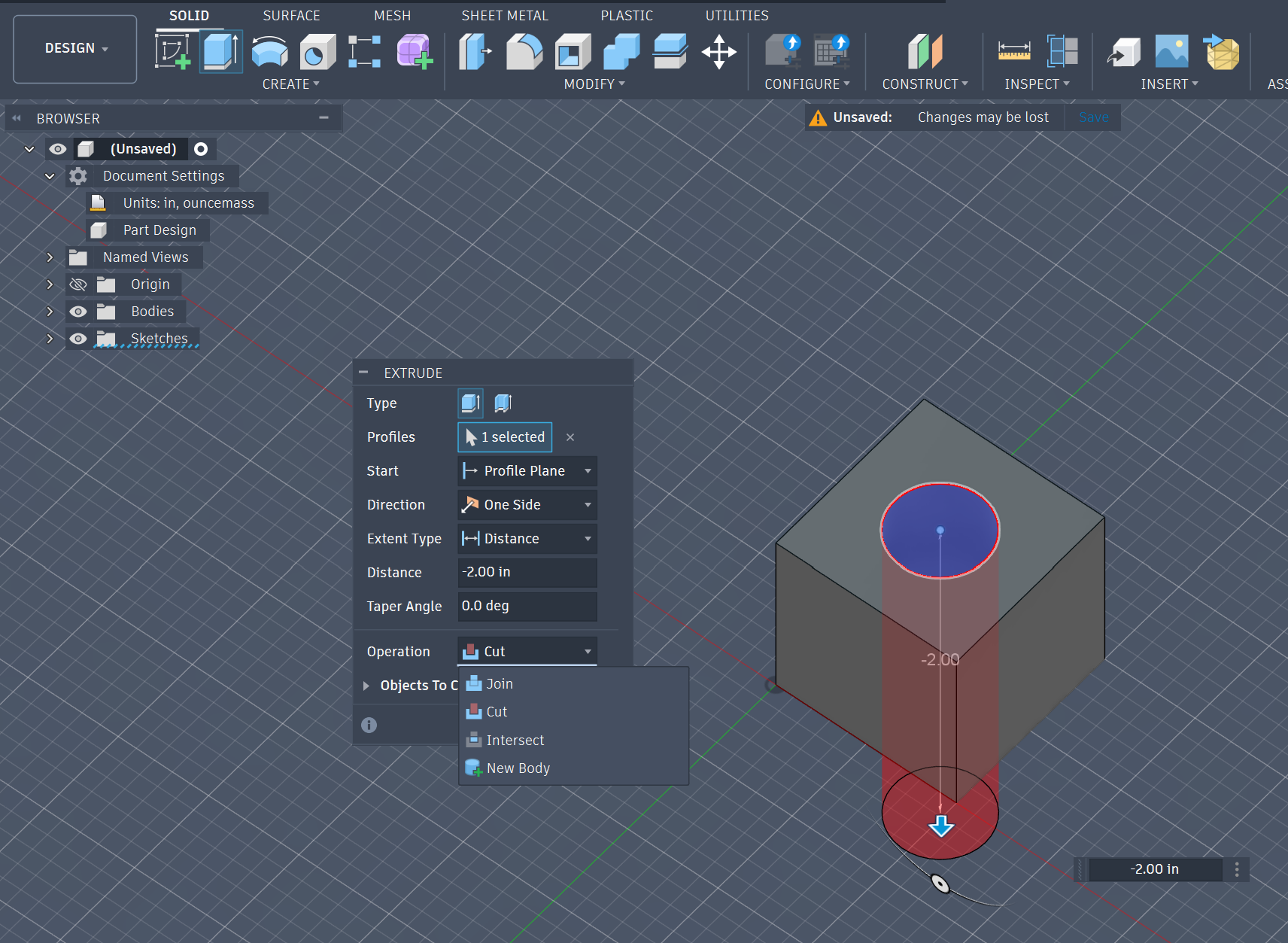
  7. Again, go to solids, and click extrude, but this time, we will change the setting of the small menu from New Body to Cut. Enter the desired cut length or press through all, and press enter.

  8. Yayyy we have a cube with a hole in it. You made your first part!


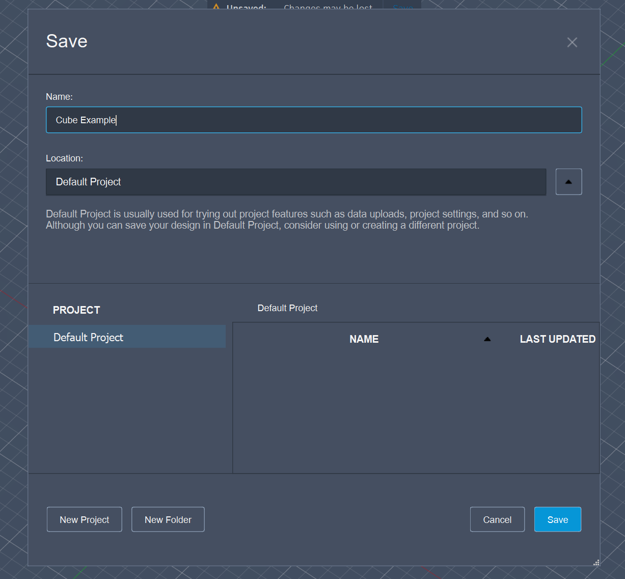
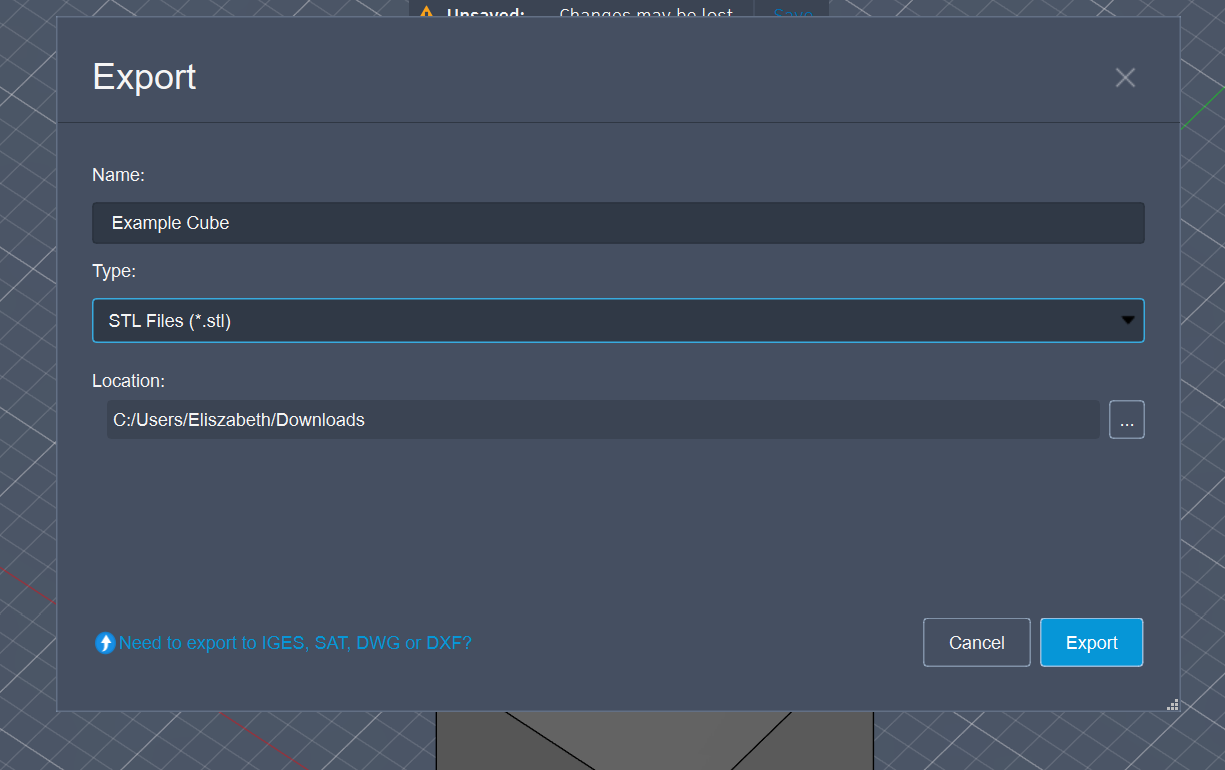
  9. Now save your part, and export it as an STL file. We use STL files to 3D print your designs!


Import STL File Into a Slicer.

3D printers work by building objects layer by layer from a digital design.

Here’s the simple flow:

  1. Design – You make a 3D model in CAD (like Fusion 360).

  2. Slice – A slicer turns that model into thin layers and instructions.

  3. Print – The printer follows those instructions, laying down material one layer at a time until the part is finished.

Think of it like a super-precise hot glue gun controlled by a robot, stacking thousands of tiny hot glue layers to make a solid object.We use BambuLabs, but you can use any software, it all works the same. 

For the most basic print of your life, just import your STL of the cube, change only what printer you have, and the filament type, press slice plate, and then print plate.

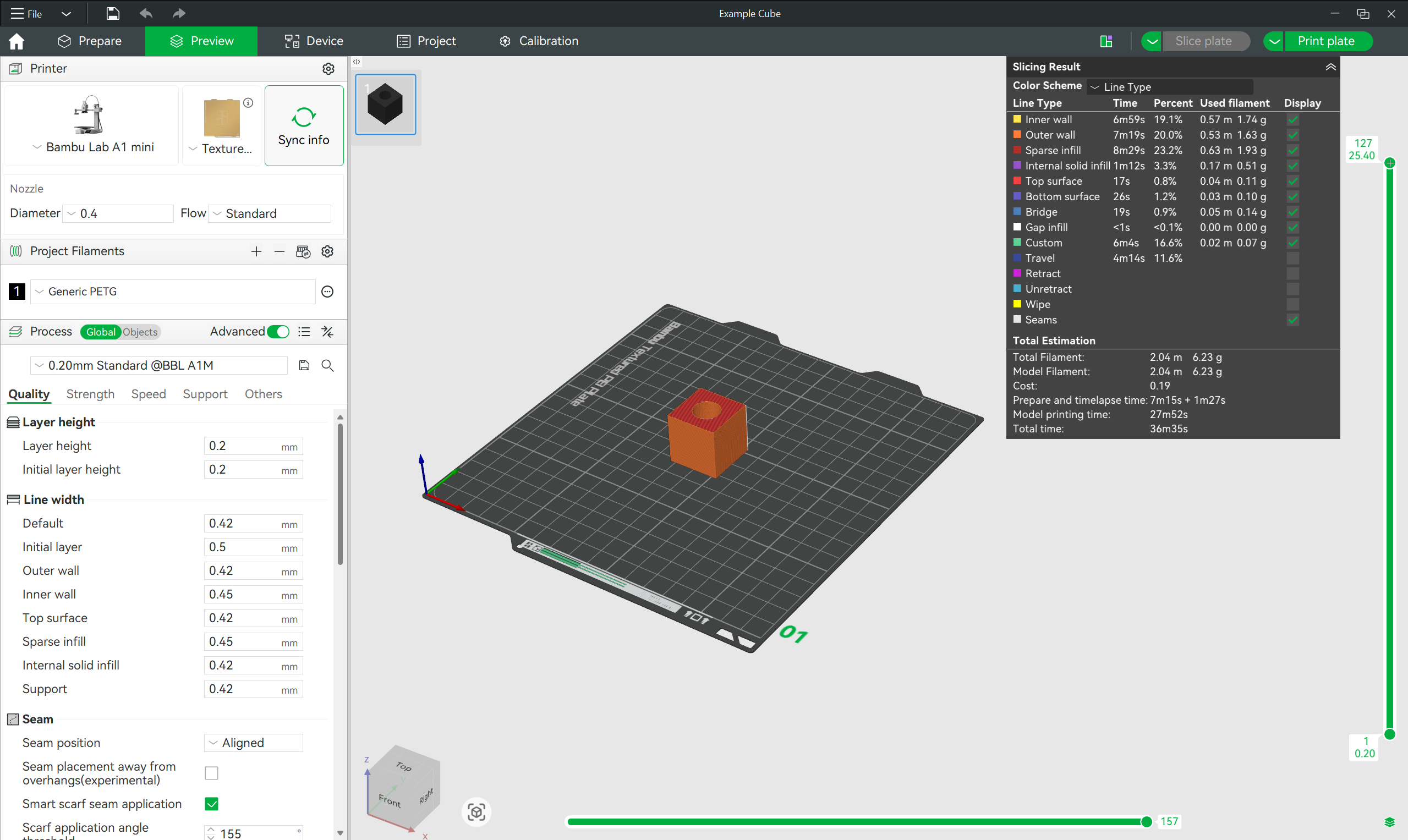
CUBEEEEEEEEEEEEE, you can have your arm pick this up now!

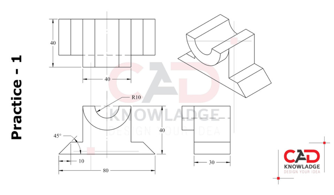
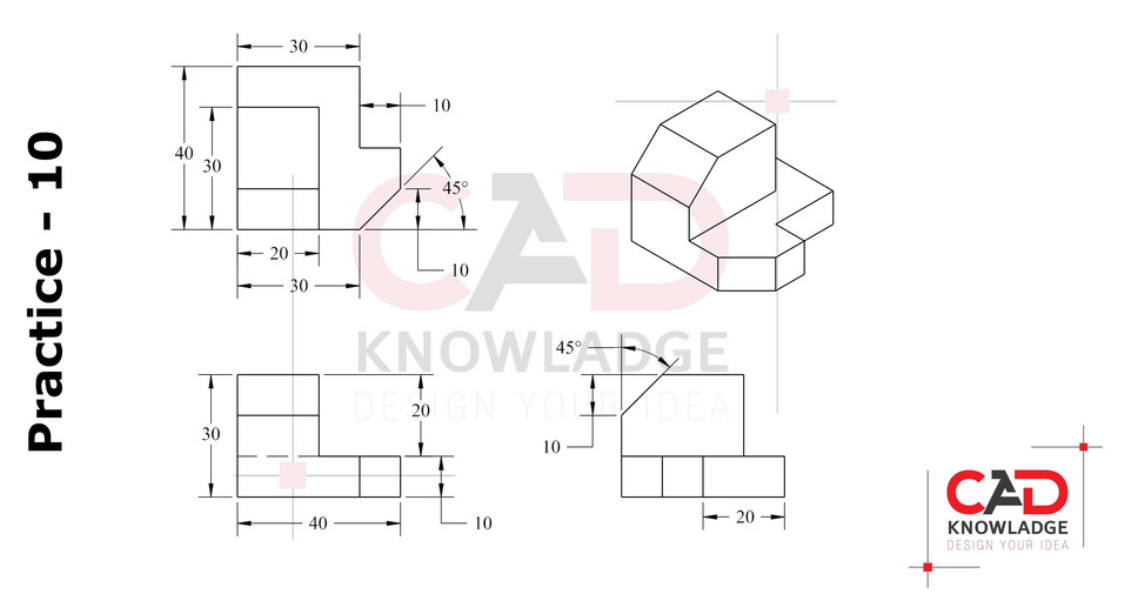
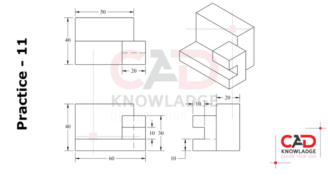
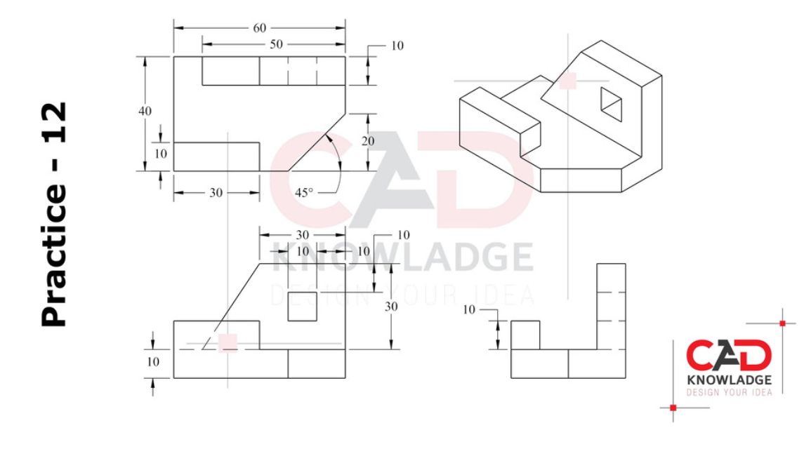
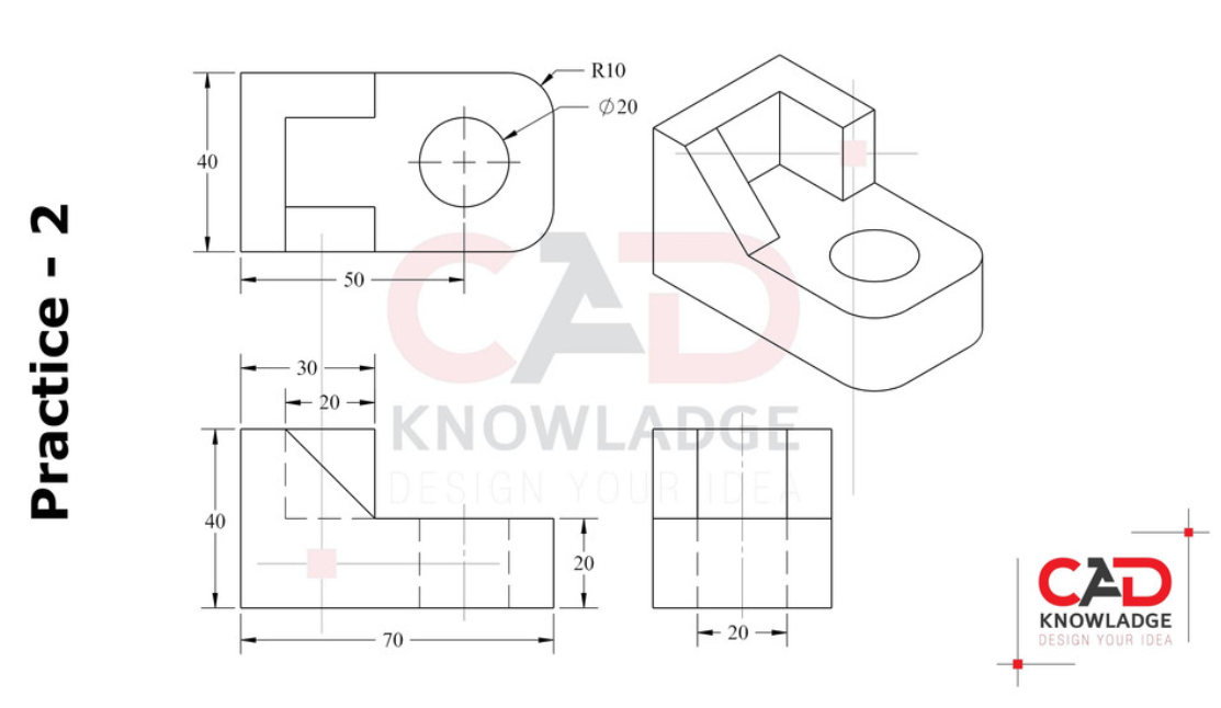
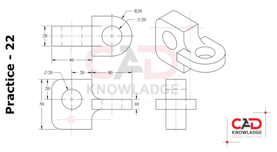
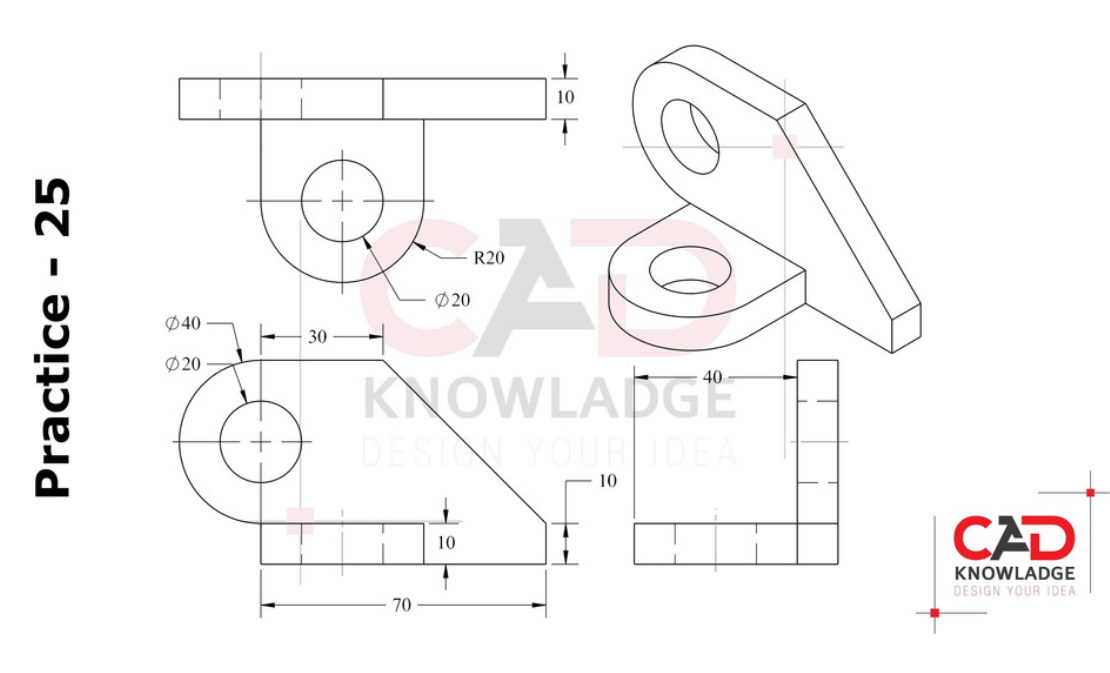
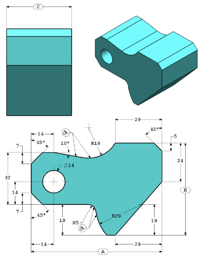
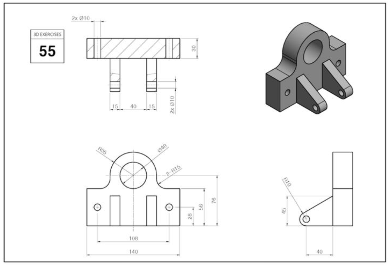
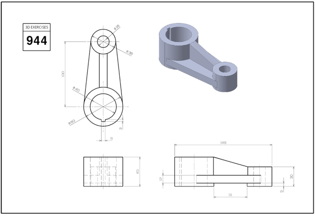
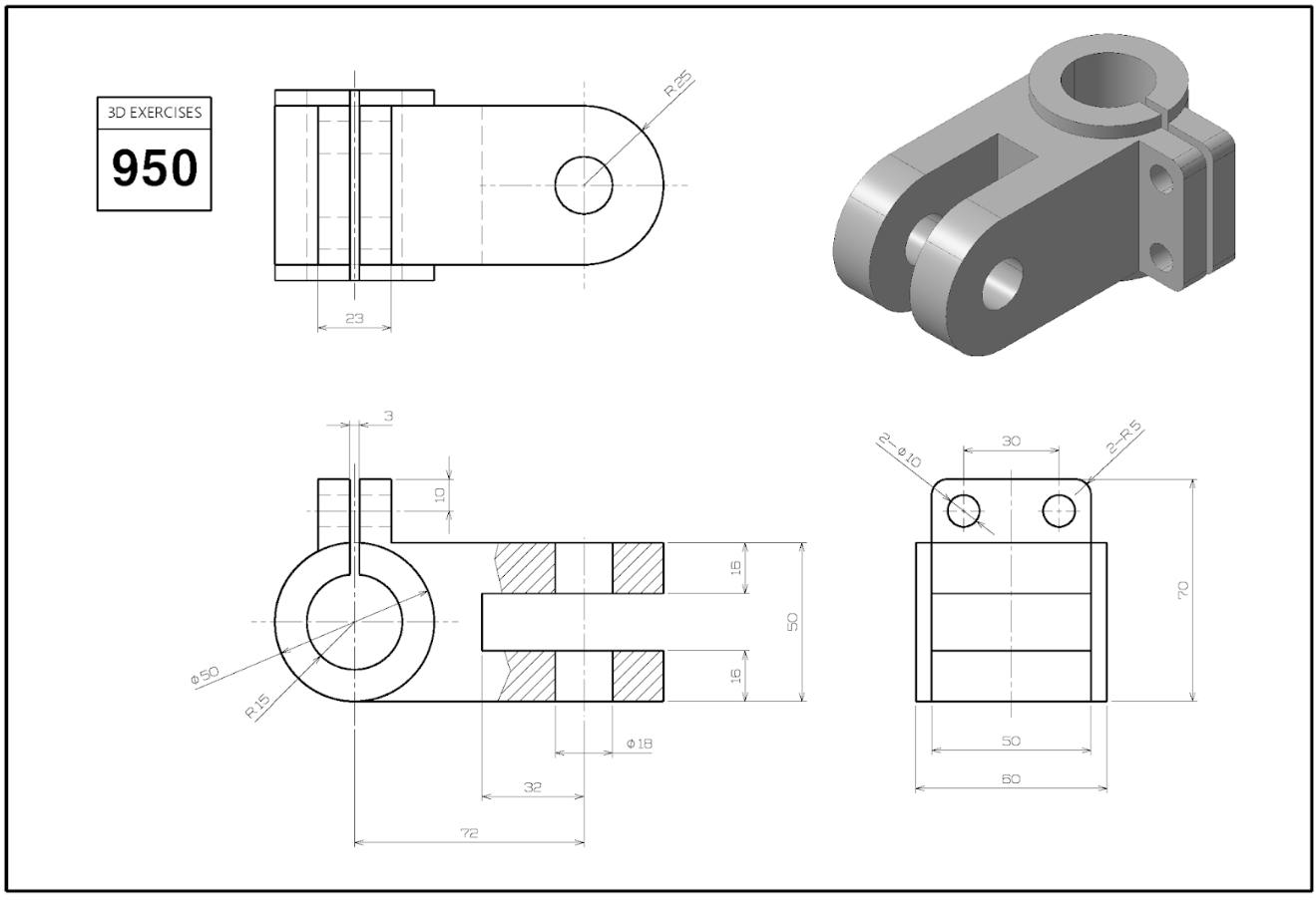
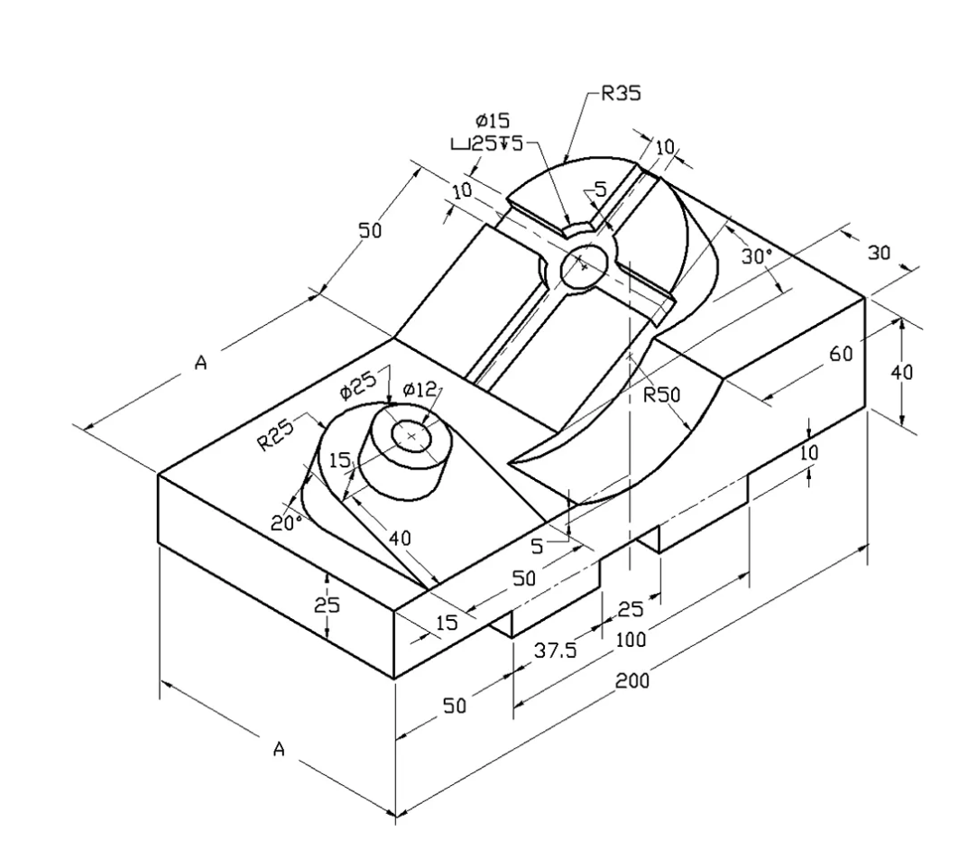
Okay, now I want you to go just press all the buttons in Fusion for a little while, explore the software. Break things, discover, then make a few of these parts for practice. The more you do the better off you'll be 🙂

If a dimension is missing (A,B,C etc), use engineering judgement and eyeball a number.

Everything is in mm, so practice changing your software to be in mm (you can change this back later to inches).

Oh and...before starting a part, really look at it first, think about how to approach it, which is the best view (front, side, top) to start the 2D sketch to turn it 3D?

For example, for Practice 1 I would sketch the front face, extrude it, then do that little semicircle that extrudes out.

Have fun!!! It gets really addicting once you get into it :))