
Check your workspace first.
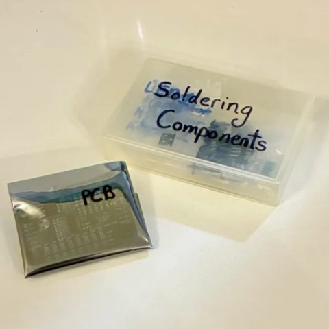
When working with heated objects, first make sure your workspace is level and clean. Gather the main PCB and resistors you will be soldering.
Before You Start: Make sure you are working in a ventilated workspace. Working with soldering irons or heated tools is a burn hazard.╰┈➤ Proceed to Section 2: Soldering Iron Setup
Set up your soldering iron.
Set the temperature: Set soldering iron to ~650°F-800°F. The hotter you set your temp, the faster you will need to move because the solder will flow much easier, but you'll be at a higher risk of burning your components or board. However, too cold and you'll have trouble soldering. Try 700°F to start.
Preheat the iron: Allow the soldering iron to fully heat.
If you are not actively using your iron, put it down, or you might accidently burn yourself or something!╰┈➤ Proceed to Step 3: What to Solder: 10k Ohm Resistors.
What to solder?
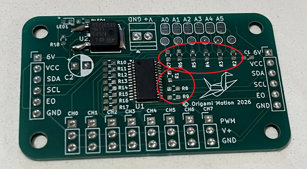
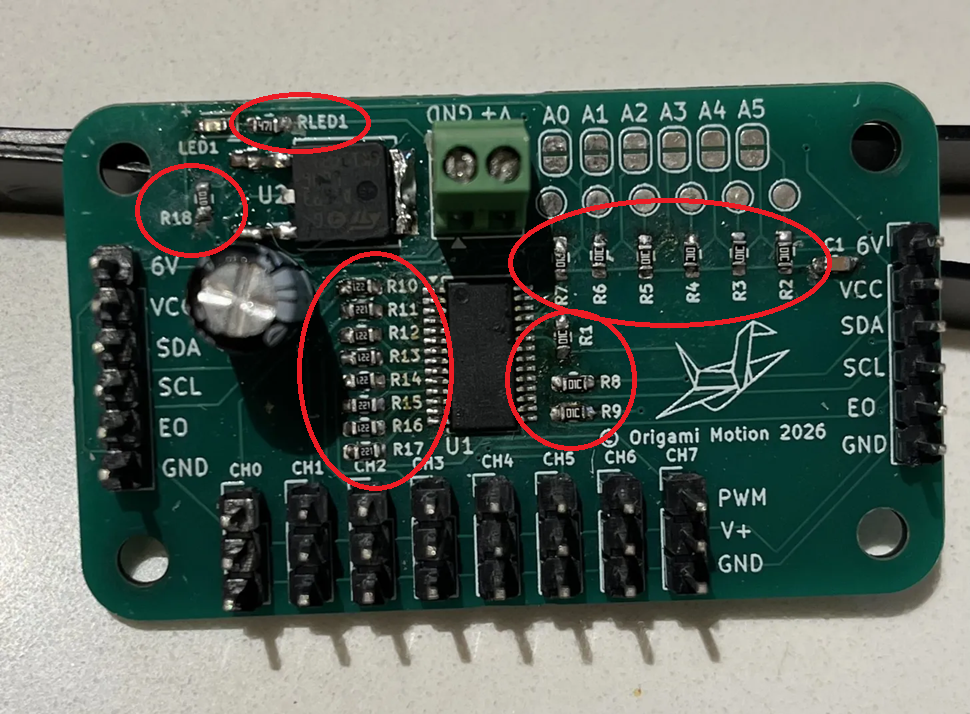
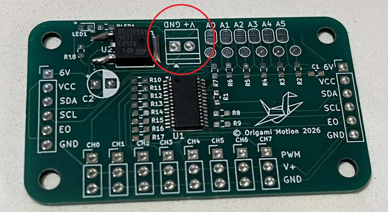
The main PCB in your kit will come looking like this: with U1 & U2 already pre-soldered.
DO NOT TOUCH YOUR HOT IRON TO THESE CHIPS AS YOU SOLDER! BE CAREFUL AND MINDFUL OF YOUR MOVEMENTS. THEY WILL BURN OR MELT WITHIN A FEW SECONDS OF CONTACT. U1 is the PWM driver chip. It's what sends control signals to your servos. XXXX
The U2 chip is basically an oopsie control. If you accidently plug power into ground and ground into power at any point, it won't instantly fry everything.
You will be soldering these 603 sized 10k Ohm resistors.
R1, R2, R3, R4, R5, R6, R7, R8, R9
Warning: Make sure you are using the correct value, or your board will not work!
U1 is the PWM driver chip. It's what sends control signals to your servos. XXXX
The U2 chip is basically an oopsie control. If you accidently plug power into ground and ground into power at any point, it won't instantly fry everything.
You will be soldering these 603 sized 10k Ohm resistors.
R1, R2, R3, R4, R5, R6, R7, R8, R9
Warning: Make sure you are using the correct value, or your board will not work!
 The direction does not matter for resistors, but black side with labeling is top, white is down to the board.
 Warning: Don't forget to turn your soldering iron off when you're done using it! You are not Elmo!

╰┈➤ Proceed to Step 4: What to Solder: 220 Ohm Resistors.
What to solder?
You will be soldering these 603 sized 220 Ohm resistors. R10, R11, R12, R13, R14, R15, R16, R17 Warning: Make sure you are using the correct value, or your board will not work!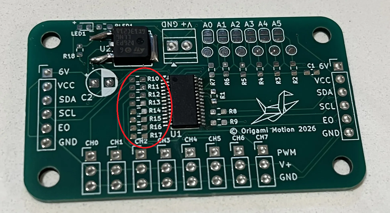 The direction does not matter for resistors, but black side with labeling is top, white is down to the board.
Warning: Don't forget to turn your soldering iron off when you're done using it! You are not Elmo!
The direction does not matter for resistors, but black side with labeling is top, white is down to the board.
Warning: Don't forget to turn your soldering iron off when you're done using it! You are not Elmo!
╰┈➤ Proceed to Step 5: What to Solder: 100k Ohm Resistors.
What to solder?
You will be soldering this 603 sized 100k Ohm resistor. R18 Warning: Make sure you are using the correct value, or your board will not work!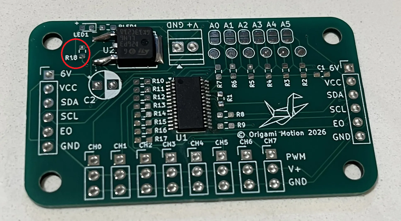 The direction does not matter for resistors, but black side with labeling is top, white is down to the board.
Warning: Don't forget to turn your soldering iron off when you're done using it! You are not Elmo!
The direction does not matter for resistors, but black side with labeling is top, white is down to the board.
Warning: Don't forget to turn your soldering iron off when you're done using it! You are not Elmo!
╰┈➤ Proceed to Step 6: What to Solder: 470 Ohm Resistors.
What to solder?
You will be soldering this 603 sized 470 Ohm resistor. RLED1 Warning: Make sure you are using the correct value, or your board will not work!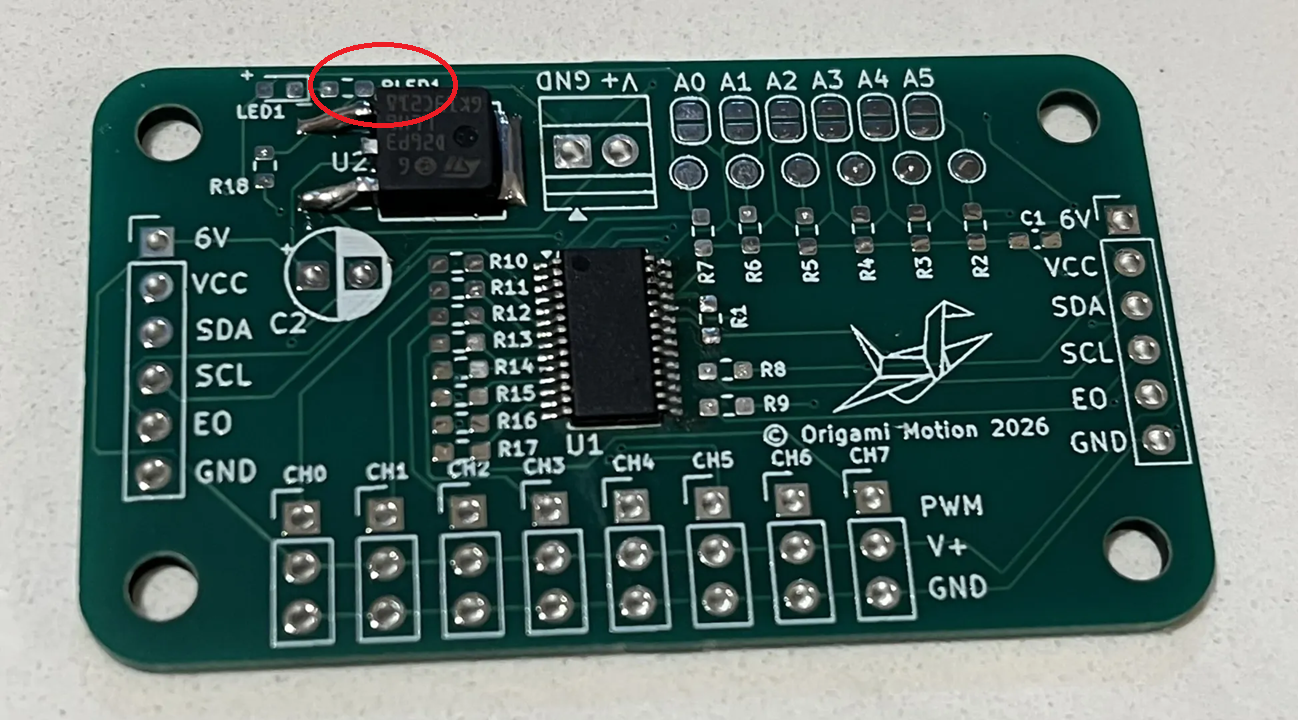 The direction does not matter for resistors, but black side with labeling is top, white is down to the board.
Warning: Don't forget to turn your soldering iron off when you're done using it! You are not Elmo!
The direction does not matter for resistors, but black side with labeling is top, white is down to the board.
Warning: Don't forget to turn your soldering iron off when you're done using it! You are not Elmo!
╰┈➤ Proceed to Step 7: How to Solder.
How to solder?
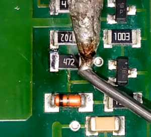
Do not solder alone, be safe and have a buddy. When using helping hands, only clamp to the corners. DO NOT clamp onto any traces, vias, pads, or you could risk damaging the board's function. 1. Apply a small amount of solder to one side of the resistor pad.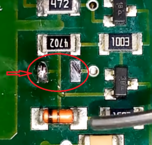 2. Apply some flux.
3. Attach the resistor using tweezers in one hand, then remelt the solder with an iron in your other hand.
2. Apply some flux.
3. Attach the resistor using tweezers in one hand, then remelt the solder with an iron in your other hand.
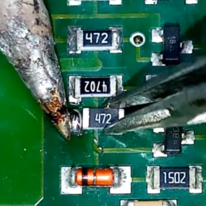 4. Let it cool and harden in place for a sec, so it stays put.
5. Flip the board around as needed, then apply solder to the other pad.
4. Let it cool and harden in place for a sec, so it stays put.
5. Flip the board around as needed, then apply solder to the other pad.
📌 Pro Tip: You can use hydrogen peroxide to clean the boards of all the flux after.
Watch this video for a great explanation/demo of how to solder SMDs using a soldering iron.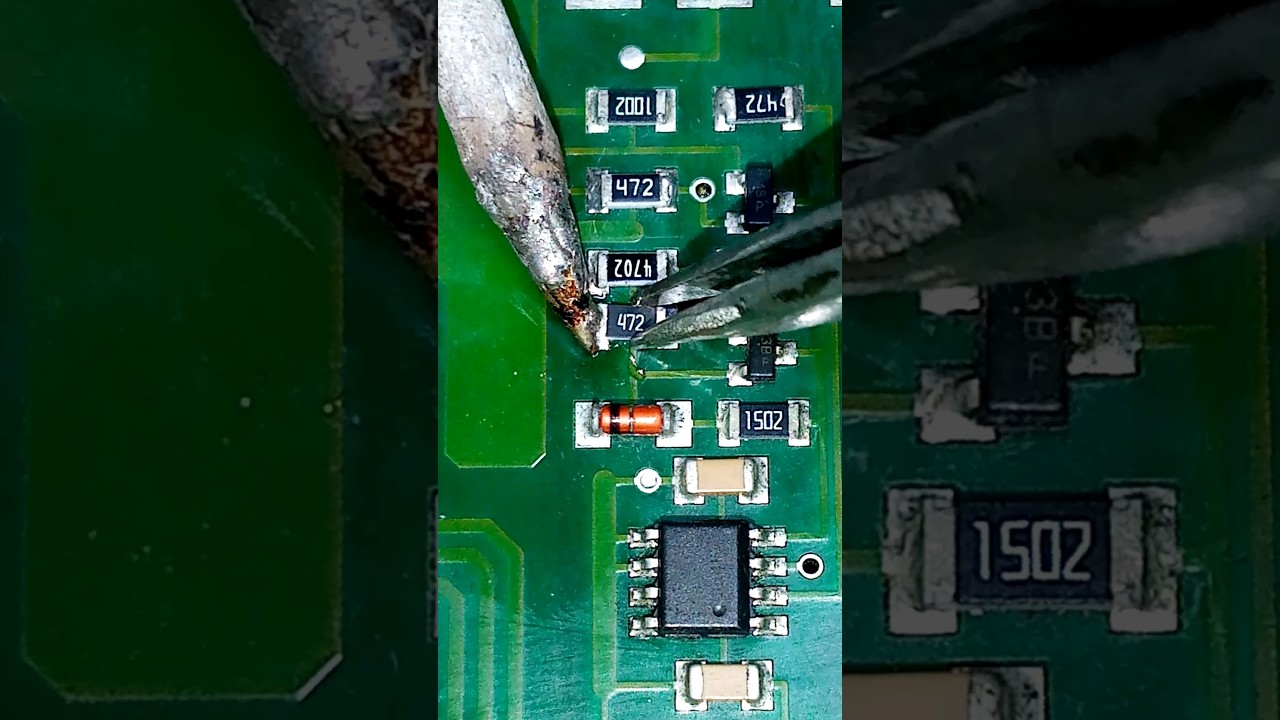
Click to watch a short example video.
╰┈➤ Proceed to Step 8: Quick Check.
Quick Check!
Yayyy - You just did most of the hard stuff! This is how it should look like after you're done soldering R1-9 (10k Ohms), R10-17 (220 Ohms), R18 (100k Ohms), and RLED1 (470 Ohm).
Reference:

That was pretty tough, great job getting that all done!
Now go do three toe touches, and one big stretch! Did you do it? Better have done it... Pablo knows all.... and will be mad at you!

╰┈➤ Proceed to Section 4: Soldering SMD Capacitors.
Check your workspace first.
When working with heated objects, first make sure your workspace is level and clean. Gather the main PCB and the C1 capacitor you will be soldering.
Before You Start: Make sure you are working in a ventilated workspace. Working with soldering irons or heated tools is a burn hazard.╰┈➤ Proceed to Step 2: Soldering Iron Setup.
Set up your soldering iron.
Set the temperature: Set soldering iron to ~650°F-800°F. The hotter you set your temp, the faster you will need to move because the solder will flow much easier, but you'll be at a higher risk of burning your components or board. However, too cold and you'll have trouble soldering. Try 700°F to start.
Preheat the iron: Allow the soldering iron to fully heat.
If you are not actively using your iron, put it down, or you might accidently burn yourself or something!╰┈➤ Proceed to Step 3: How to Solder
How to solder?
Do not solder alone, be safe and have a buddy. When using helping hands, only clamp to the corners. DO NOT clamp onto any traces, vias, pads, or you could risk damaging the board's function. 1. Apply a small amount of solder to one side of the capacitor pad.
2. Apply some flux.
3. Attach the capacitor using tweezers in one hand, then remelt the solder with an iron in your other hand.
4. Let it cool and harden in place for a sec, so it stays put.
5. Flip the board around as needed, then apply solder to the other pad.
📌 Pro Tip: You can use hydrogen peroxide to clean the boards of all the flux after.
Watch this video for a great explanation/demo of how to solder SMDs using a soldering iron.
Click to watch a short example video.
╰┈➤ Proceed to Step 4: What to Solder.
What to solder?
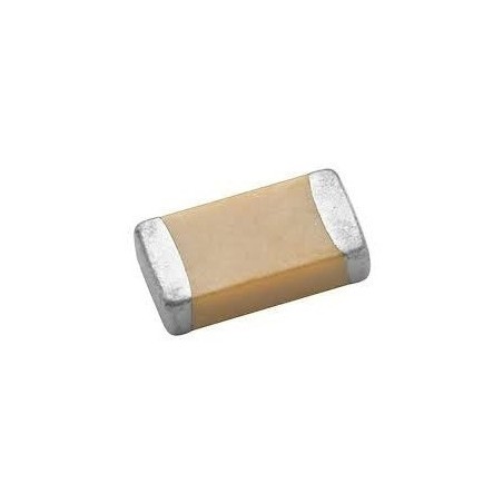
You will be soldering this singular C1 10uF capacitor.
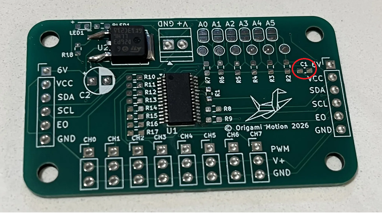 The direction does not matter for these small SMD capacitors.
 THEY DO MATTER ON THE BIG CYLINDRICAL ONE (C2) you will solder later.
Warning: Don't forget to turn your soldering iron off when you're done using it! You are not Elmo!
THEY DO MATTER ON THE BIG CYLINDRICAL ONE (C2) you will solder later.
Warning: Don't forget to turn your soldering iron off when you're done using it! You are not Elmo!
╰┈➤ Proceed to Step 5: Quick Check
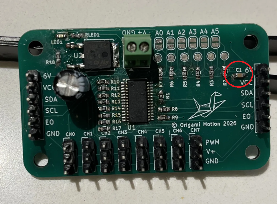
Quick Check!
This is how it should look like after you're done.
Check your workspace first.
When working with heated objects, first make sure your workspace is level and clean. Gather the main PCB and the LED you will be soldering.
Before You Start: Make sure you are working in a ventilated workspace. Working with soldering irons or heated tools is a burn hazard.╰┈➤ Proceed to Step 2: Soldering Iron Setup.
Set up your soldering iron.
Set the temperature: Set soldering iron to ~650°F-800°F. The hotter you set your temp, the faster you will need to move because the solder will flow much easier, but you'll be at a higher risk of burning your components or board. However, too cold and you'll have trouble soldering. Try 700°F to start.
Preheat the iron: Allow the soldering iron to fully heat.
If you are not actively using your iron, put it down, or you might accidently burn yourself or something!╰┈➤ Proceed to Step 3: How to Solder
How to solder?
Do not solder alone, be safe and have a buddy.
When using helping hands, only clamp to the corners. DO NOT clamp onto any traces, vias, pads, or you could risk damaging the board's function.
1. Apply a small amount of solder to one side of the LED pad.
2. Apply some flux.
3. Attach the LED using tweezers in one hand, then remelt the solder with an iron in your other hand.
4. Let it cool and harden in place for a sec, so it stays put.
5. Flip the board around as needed, then apply solder to the other pad.
📌 Pro Tip: You can use hydrogen peroxide to clean the boards of all the flux after.
Watch this video for a great explanation/demo of how to solder SMDs using a soldering iron.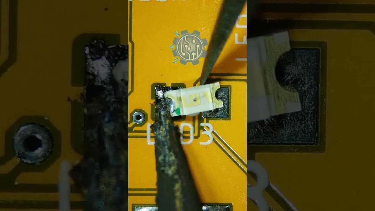
Click to watch a short example video.
╰┈➤ Proceed to Step 4: What to Solder.
What to solder?
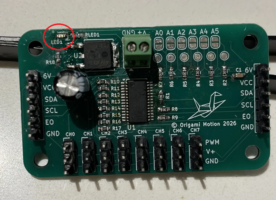
You will be soldering this singular LED1.
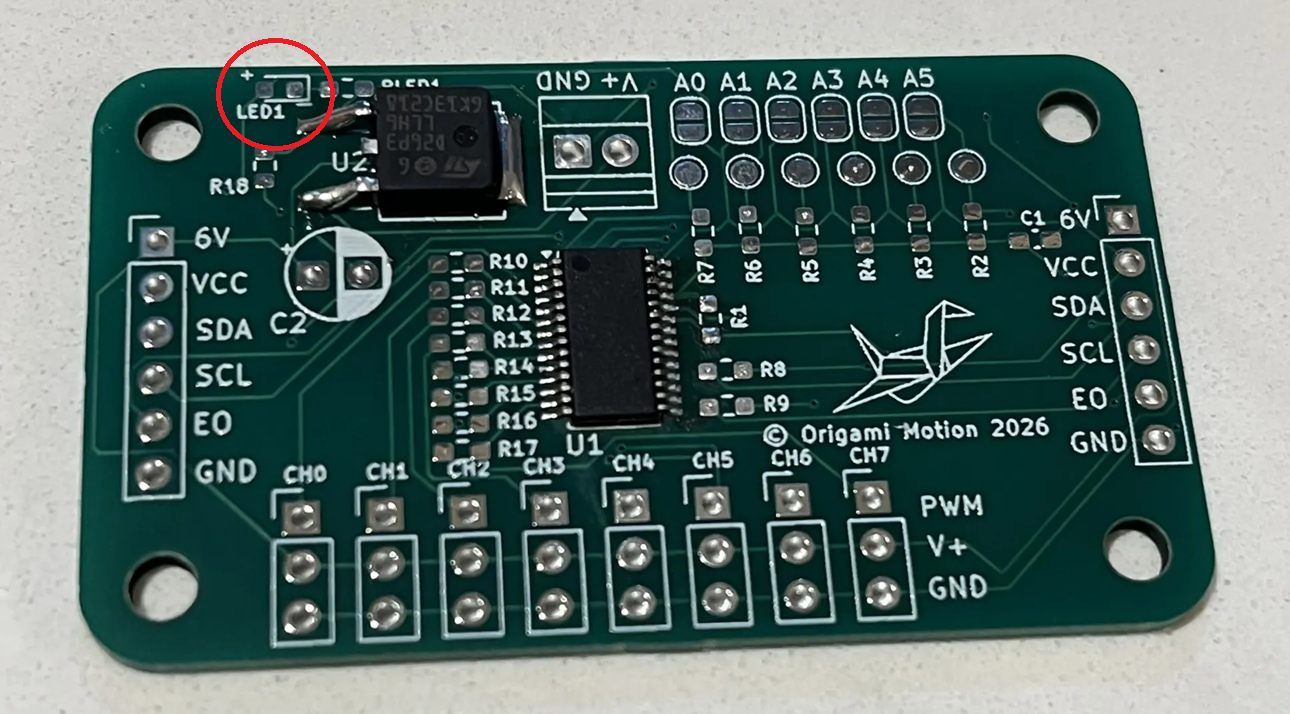
Warning: Direction and orientation matters!
All of them look a little different, but if you flip the LED upside down, look for the side with the green line, dot or arrow. GREEN for GROUND or the NEGATIVE (-). The clear side is up, and the side with the green dot/white pad is down to the board.
The board is marked with which side is + and which is -.
DO NOT TOUCH THE IRON ON THE CLEAR TOP OR RISK BURNING THE LED, ONLY THE SIDES.

![]()
Warning: Don't forget to turn your soldering iron off when you're done using it!

╰┈➤ Proceed to Step 5: Quick Check
Quick Check!
This is how it should look like after you're done.
Check your workspace first.
When working with heated objects, first make sure your workspace is level and clean. Gather the main PCB and header pins you will be soldering.
Before You Start: Make sure you are working in a ventilated workspace. Working with soldering irons or heated tools is a burn hazard.╰┈➤ Proceed to Step 2: Soldering Iron Setup
Set up your soldering iron.
Set the temperature: Set soldering iron to ~650°F-800°F. The hotter you set your temp, the faster you will need to move because the solder will flow much easier, but you'll be at a higher risk of burning your components or board. However, too cold and you'll have trouble soldering. Try 700°F to start.
Preheat the iron: Allow the soldering iron to fully heat.
If you are not actively using your iron, put it down, or you might accidently burn yourself or something!╰┈➤ Proceed to Step 3: What to Solder
What to solder?
You will be soldering these header pins. Why header pins before the terminal block or C2? I like to do shortest things first, it's easier - but that's personal preference.
8x set of 3 header pins 2x set of 6 header pins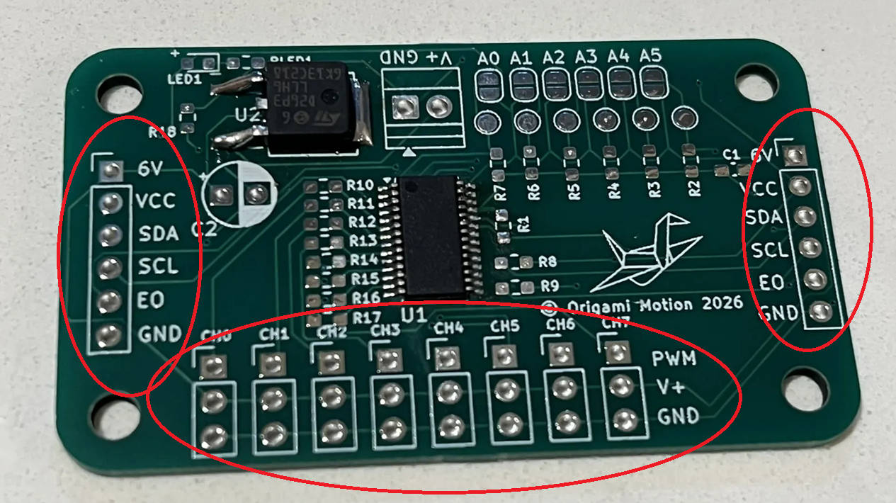 Warning: Don't forget to turn your soldering iron off when you're done using it! You are not Elmo!
╰┈➤ Proceed to Step 4: How to Solder.
How to solder?
When using helping hands, only clamp to the corners. DO NOT clamp onto any traces, vias, pads, or you could risk damaging the board's function. 1. Using angle cutters or pliers, snap off the amount of pins you need. You can use your finger nail too. Be careful to not launch it into your eye. Do not solder alone, be safe and have a buddy, so if you do launch a header pin into your eye, someone else can go get help. 2. Apply some flux to the holes on the PCB. 3. If you have a breadboard, you can use it to hold the pins in place to solder (see video). If not, attach all of the pins, and flip the board upside down, bracing the low side with something. Short side goes in the holes. 4. Solder one pin of each of the sets first, let it cool and harden so the whole row stays put. Make sure the pins are not crooked at an angle! This is why you only solder one pin first, so you can remelt and adjust as needed. 5. Go back and solder the rest of the pins. Watch this video for a great explanation/demo of how to solder header pins using a soldering iron.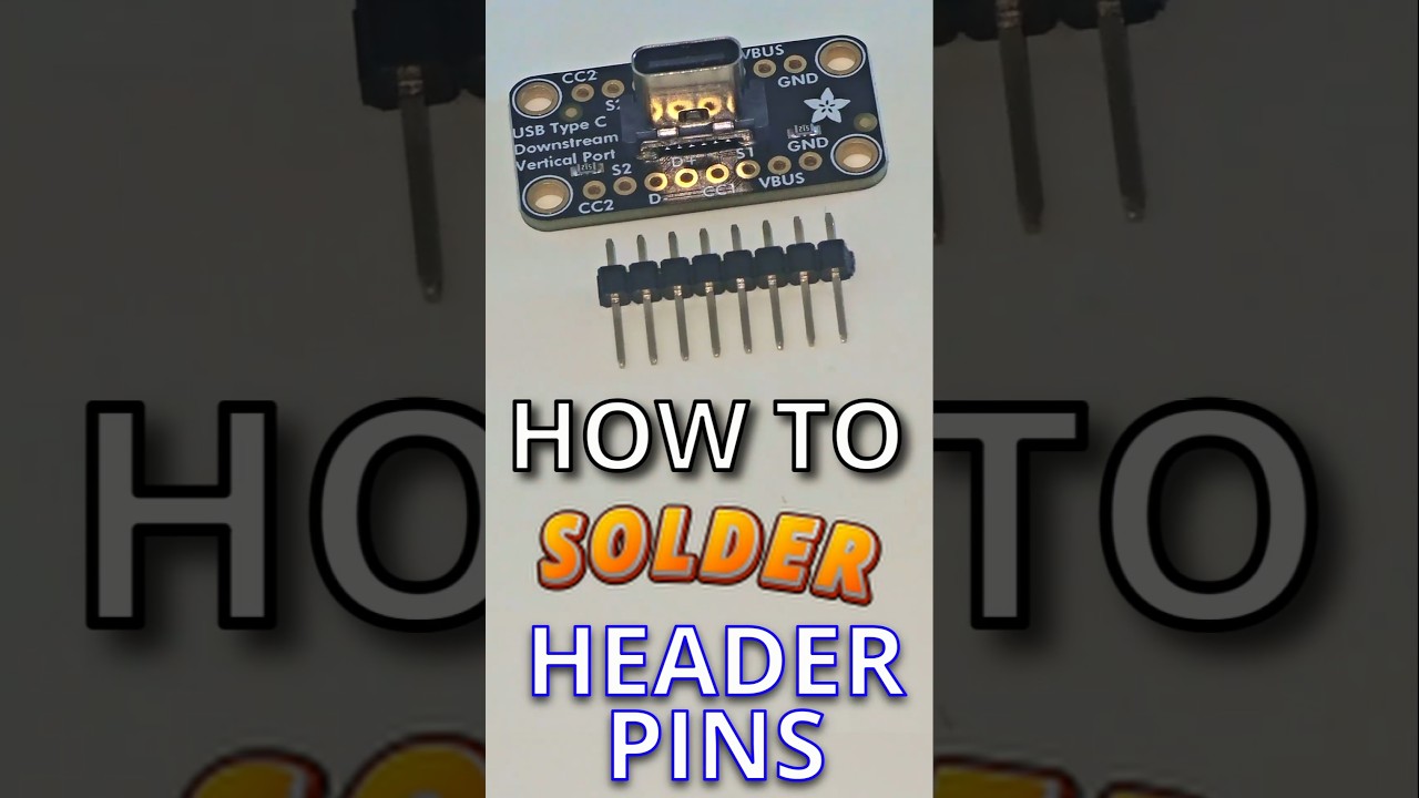
Click to watch a short example video.
╰┈➤ Proceed to Step 5: Quick Check.
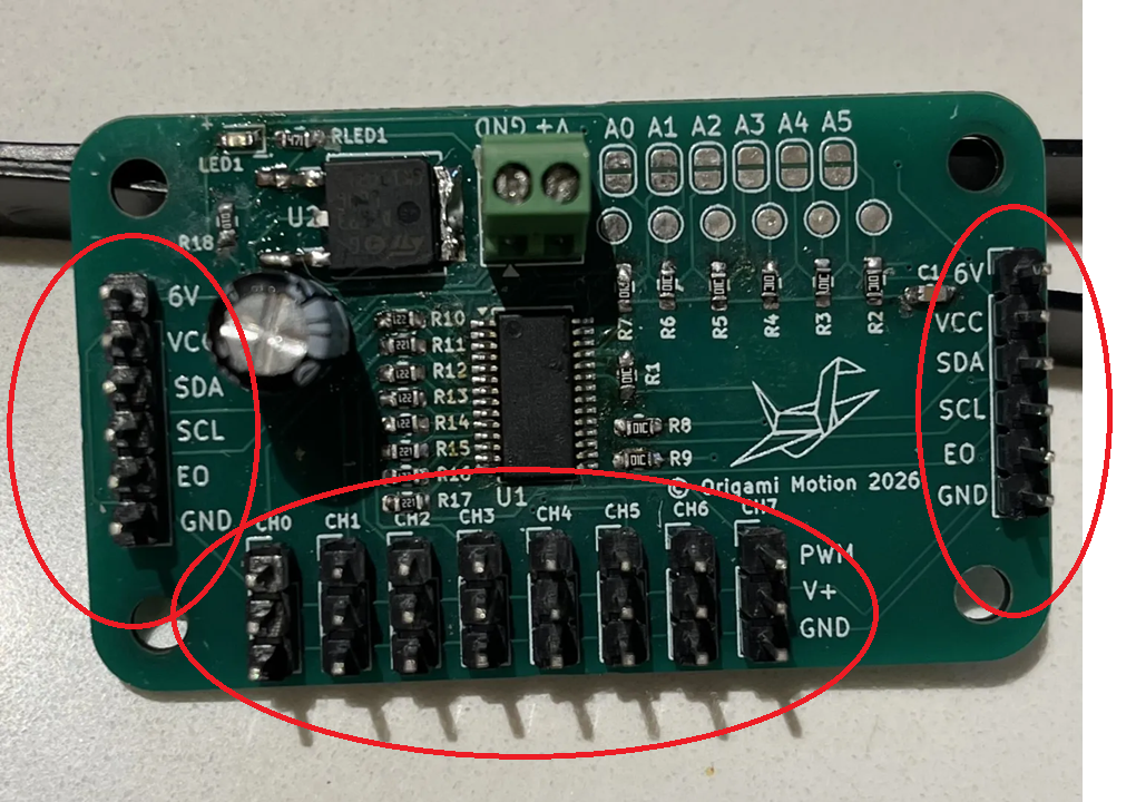
Quick Check!
This is how it should look like after you're done.
What is a Terminal Block?
A terminal block is a small connector that lets you securely attach wires to a circuit or device without soldering.
Think of it like a tiny clamp for wires: you loosen a screw, put the wire in, tighten it, and it stays put. It’s commonly used to connect power, motors, or sensors safely and neatly.
There is how you will connect your board to your 6V power supply.╰┈➤ Proceed to Step 2: Check your Workspace.
Check your workspace first.
When working with heated objects, first make sure your workspace is level and clean. Gather the main PCB and terminal block you will be soldering.
Before You Start: Make sure you are working in a ventilated workspace. Working with soldering irons or heated tools is a burn hazard.╰┈➤ Proceed to Step 3: Soldering Iron Setup.
Set up your soldering iron.
Set the temperature: Set soldering iron to ~650°F-800°F. The hotter you set your temp, the faster you will need to move because the solder will flow much easier, but you'll be at a higher risk of burning your components or board. However, too cold and you'll have trouble soldering. Try 700°F to start.
Preheat the iron: Allow the soldering iron to fully heat.
If you are not actively using your iron, put it down, or you might accidently burn yourself or something!╰┈➤ Proceed to Step 3: What to Solder.
What to solder?
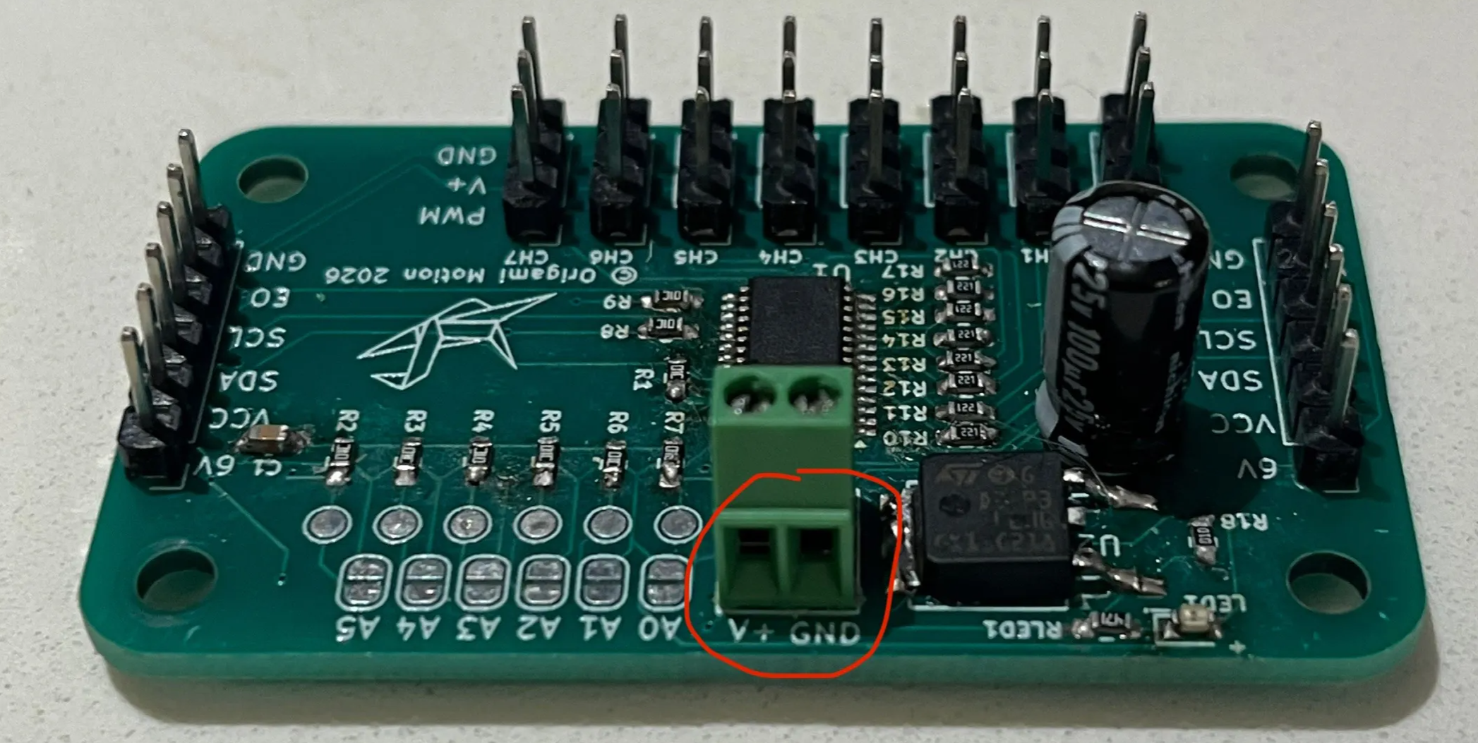
You will be soldering this terminal block.
╰┈➤ Proceed to Step 3: How to Solder.
How to solder?
Do not solder alone, be safe and have a buddy. When using helping hands, only clamp to the corners. DO NOT clamp onto any traces, vias, pads, or you could risk damaging the board's function.- Insert the terminal block so that the holes where you attach the wires to are accessible from the outside of the board.
 2. Flip it upside down. Brace it as needed with an object, or add a little tape to hold it in place.
3. Apply flux to the leads/through holes where the terminal block is attached.
4. Apply solder to one lead, then make sure the terminal block is flushed to the board. If not, adjust, then solder the other side.
2. Flip it upside down. Brace it as needed with an object, or add a little tape to hold it in place.
3. Apply flux to the leads/through holes where the terminal block is attached.
4. Apply solder to one lead, then make sure the terminal block is flushed to the board. If not, adjust, then solder the other side.
╰┈➤ Proceed to Step 6: Quick Check.
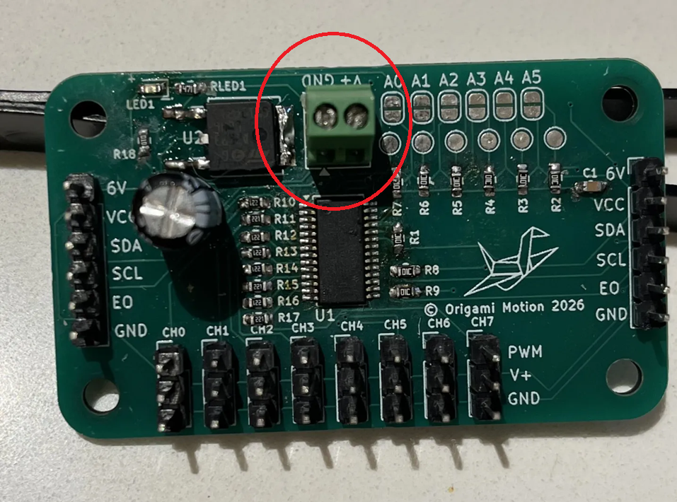
Quick Check!
This is how it should look like after you're done.
Check your workspace first.
When working with heated objects, first make sure your workspace is level and clean. Gather the main PCB and the C2 cap you will be soldering.
Before You Start: Make sure you are working in a ventilated workspace. Working with soldering irons or heated tools is a burn hazard.╰┈➤ Proceed to Step 2: Soldering Iron Setup
Set up your soldering iron.
Set the temperature: Set soldering iron to ~650°F-800°F. The hotter you set your temp, the faster you will need to move because the solder will flow much easier, but you'll be at a higher risk of burning your components or board. However, too cold and you'll have trouble soldering. Try 700°F to start.
Preheat the iron: Allow the soldering iron to fully heat.
If you are not actively using your iron, put it down, or you might accidently burn yourself or something!╰┈➤ Proceed to Step 3: What to Solder
What to solder?
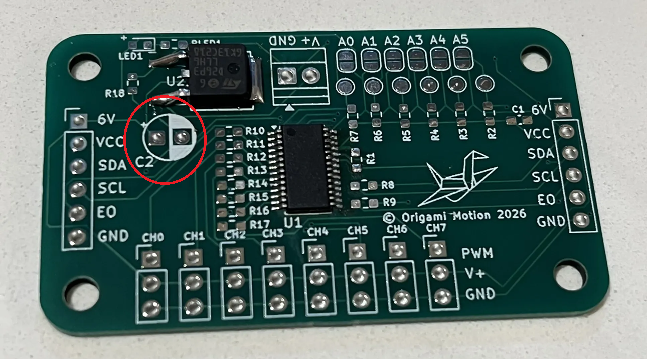
You will be soldering the C2 100uF capacitor.
Direction does matter!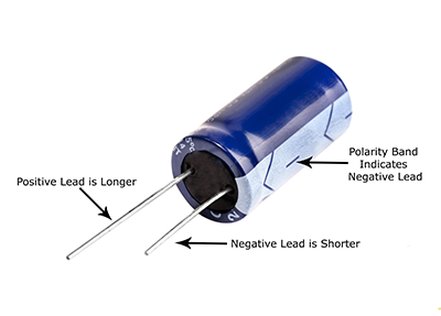 Check for the positive marking on the PCB and insert accordingly.
📌 Pro Tip: Do not touch the positive and negative leads together. If the capacitor has large enough capacitance, you'll get a nice fireworks show. The ones we give you are fine, just develop good practice habits now.
Warning: Don't forget to turn your soldering iron off when you're done using it! You are not Elmo!
╰┈➤ Proceed to Step 4: How to Solder.
How to solder?
Do not solder alone, be safe and have a buddy. When using helping hands, only clamp to the corners. DO NOT clamp onto any traces, vias, pads, or you could risk damaging the board's function. 1. Find the positive side on the board, it's labeled. Insert the capacitor longer side in the positive hole until flushed with the board 2. With a finger holding the cap in place, flip the board and bend the leads down to the board. This secures the cap in place so you can solder it. You can also tape it down (see video for reference). 3. Apply some flux. 4. Touch the tip of the hot iron to the pad and the lead, then dab in some solder. Repeat for the other lead as well. Again, try not to touch the metal iron to both leads at the same time. 5. Cut the excess length off both leads with angle cutters.📌 Pro Tip: You can use hydrogen peroxide to clean the boards of all the flux after.
Watch this video for a great explanation/demo of how to solder an electrolytic capacitor using a soldering iron.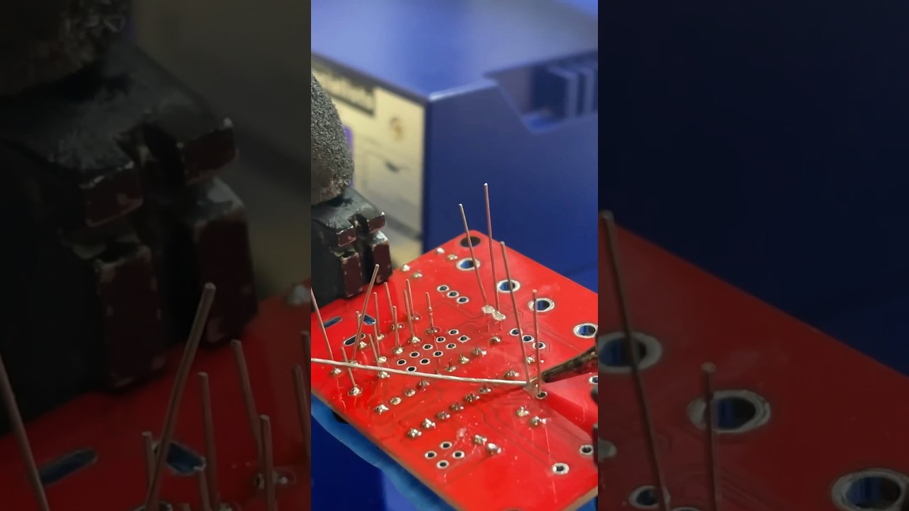
Click to watch a short example video.
╰┈➤ Proceed to Step 5: Quick Check.
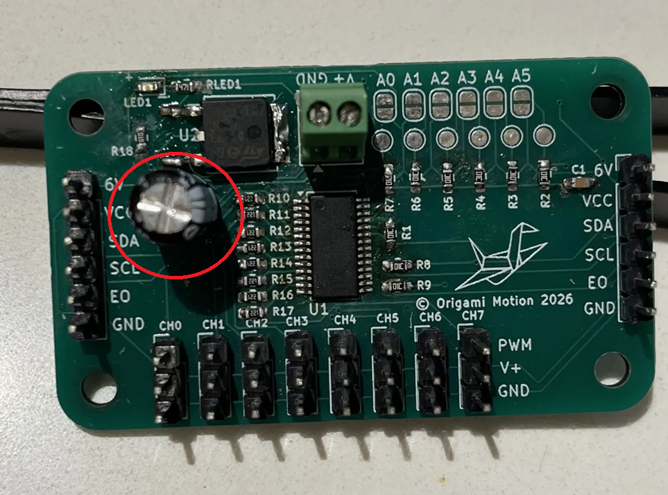
Quick Check!
This is how it should look like after you're done.

--
10. Haribo!
Enjoy your 5th pile of gummy bears now!
Watch this highly educational video on gummy bears as you enjoy your 5th pile.