What is an 805 SMD Resistor?
An SMD (Surface-Mount Device) resistor is a small electronic part that slows down electricity to protect other parts. SMD means it is soldered flat onto the board.
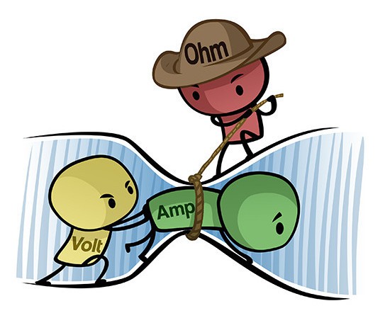
Basics of electronics:- Current (Amp): how much electricity is flowing (like water moving in a pipe)
- Voltage (Volt): how hard the electricity is being pushed (like water pressure)
- Resistance (Ohm): how much something slows the electricity down (like a narrow pipe)
805, is just a very common physical SMD size. 0805 size = 0.08 inches × 0.05 inches.
╰┈➤ Go to Step 2: Check Your Workspace
Check your workspace first.
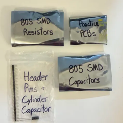
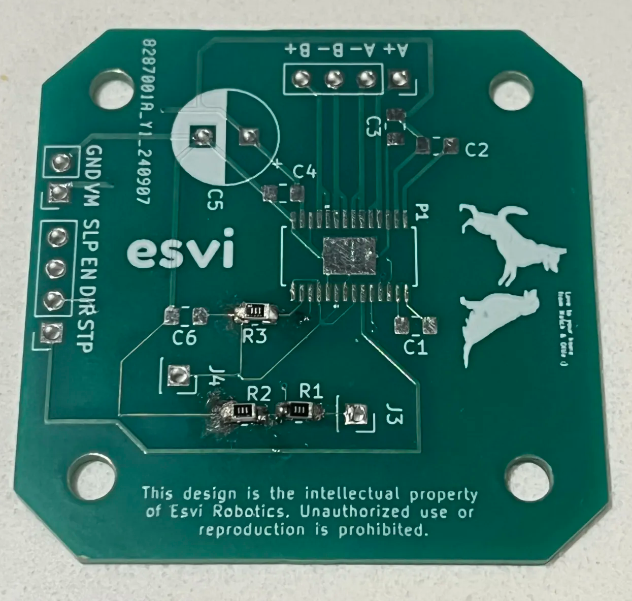
When working with heated objects, first make sure your workspace is level and clean. Gather the practice PCB and resistors you will be soldering.
Before You Start: Make sure you are working in a ventilated workspace. Working with soldering irons or heated tools is a burn hazard.╰┈➤ Go to Step 3: Soldering Iron Setup
Set up your soldering iron.
Set the temperature: Set soldering iron to ~650°F-800°F. The hotter you set your temp, the faster you will need to move because the solder will flow much easier, but you'll be at a higher risk of burning your components or board. However, too cold and you'll have trouble soldering. Try 700°F to start.
Preheat the iron: Allow the soldering iron to fully heat.
If you are not actively using your iron, put it down, or you might accidently burn yourself or something!╰┈➤ Go to Step 4: How to Solder
How to solder?
Do not solder alone, be safe and have a buddy. When using helping hands, only clamp to the corners. DO NOT clamp onto any traces, vias, pads, or you could risk damaging the board's function. 1. Apply a small amount of solder to one side of the resistor pad.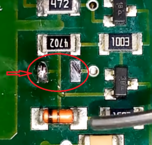 2. Apply some flux.
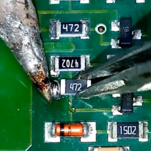
3. Attach the resistor using tweezers in one hand, then remelt the solder with an iron in your other hand. You never touch the actual top of the component with an iron, only the silver side pads, or risk burning your parts.
2. Apply some flux.
3. Attach the resistor using tweezers in one hand, then remelt the solder with an iron in your other hand. You never touch the actual top of the component with an iron, only the silver side pads, or risk burning your parts.
 4. Let it cool and harden in place for a sec, so it stays put.
5. Flip the board around as needed, then apply solder to the other pad.
4. Let it cool and harden in place for a sec, so it stays put.
5. Flip the board around as needed, then apply solder to the other pad.
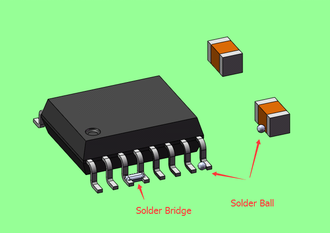
📌 Pro Tip: Bridging is BAD! Bridging on a PCB is when extra solder accidentally connects two parts that shouldn’t be connected, causing a short circuit. A short circuit is when electricity takes a wrong, easy path instead of going through the parts, which can cause things to overheat or stop working. Be extra careful this does not happen.
 Watch this video for a great explanation/demo of how to solder SMDs using a soldering iron.
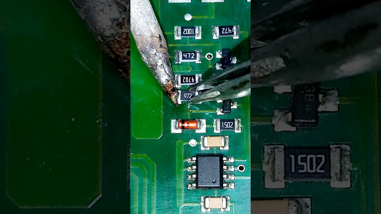
Click to watch a short example video.
╰┈➤ Go to Step 5: What to Solder
What to solder?
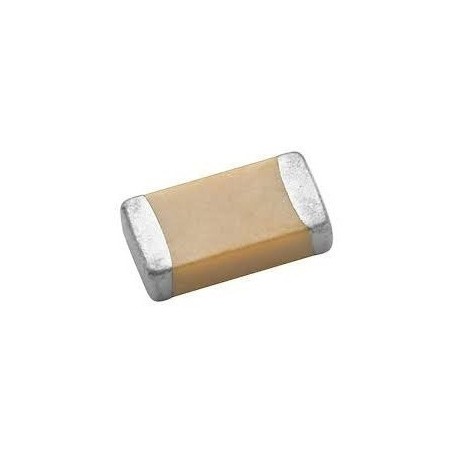
You will be soldering these three 805 sized resistors.
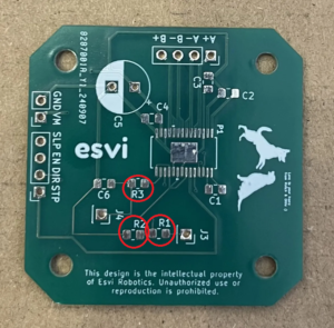 The direction does not matter for resistors, but black side with labeling is top, white is down to the board.

📌 Pro Tip: Unless you were born a robot, everyone has some level of shaky hands. Brace your arms on the edge of your work station to provide support and reduce shaking when soldering.
Warning: Don't forget to turn your soldering iron off when you're done using it! You are not Elmo!
╰┈➤ Go to Step 6: Quick Check
Quick Check!
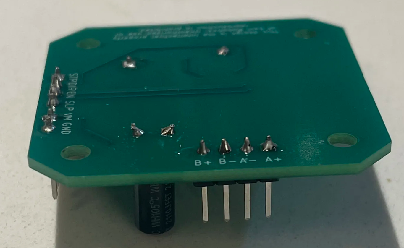
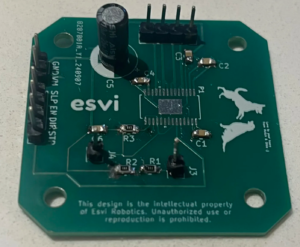
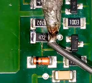
This is how it should look like after you're done.
╰┈➤ Proceed to Section 4: Soldering SMD Capacitors.
What is an 805 SMD Capacitor?
An SMD capacitor is a part that stores a small amount of electricity and then releases it later.
You can think of it like a tiny rechargeable bucket that helps smooth power and protect circuits.
╰┈➤ Go to Step 2: Check Your Workspace
Check your workspace first.
When working with heated objects, first make sure your workspace is level and clean. Gather the practice PCB and capacitors you will be soldering.
Before You Start: Make sure you are working in a ventilated workspace. Working with soldering irons or heated tools is a burn hazard.╰┈➤ Go to Step 3: Soldering Iron Setup
Set up your soldering iron.
Set the temperature: Set soldering iron to ~650°F-800°F. The hotter you set your temp, the faster you will need to move because the solder will flow much easier, but you'll be at a higher risk of burning your components or board. However, too cold and you'll have trouble soldering. Try 700°F to start.
Preheat the iron: Allow the soldering iron to fully heat.
If you are not actively using your iron, put it down, or you might accidently burn yourself or something!╰┈➤ Go to Step 4: How to Solder
How to solder?
Do not solder alone, be safe and have a buddy. When using helping hands, only clamp to the corners. DO NOT clamp onto any traces, vias, pads, or you could risk damaging the board's function. 1. Apply a small amount of solder to one side of the capacitor pad.
2. Apply some flux.
3. Attach the capacitor using tweezers in one hand, then remelt the solder with an iron in your other hand.
4. Let it cool and harden in place for a sec, so it stays put.
5. Flip the board around as needed, then apply solder to the other pad.
📌 Pro Tip: You can use hydrogen peroxide to clean the boards of all the flux after.
Watch this video for a great explanation/demo of how to solder SMDs using a soldering iron.
Click to watch a short example video.
╰┈➤ Go to Step 5: What to Solder
What to solder?
You will be soldering these five 805 sized capacitors.
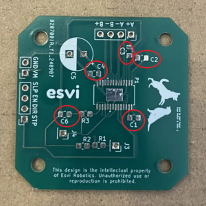 The direction does not matter for these small SMD capacitors.
 THEY DO MATTER ON THE BIG CYLINDRICAL ONE (C5) you will solder later.
📌 Pro Tip: Don't be a shrimp, or do the splits! Find a comfortable position to solder. Is it standing, sitting, criss cross applesauce somewhere? Whatever floats your boat, always solder comfortable, you'll produce better results.
Warning: Don't forget to turn your soldering iron off when not in use. This is NOT the lightbulb moment you want.
╰┈➤ Go to Step 6: Quick Check
Quick Check!
This is how it should look like after you're done.
Stop: Are your eyes sore? Do you feel lightheaded? Dizzy? That probably means you're sniffing too much lead fumes...check your ventilation...maybe go inhale some fresh air for a minute & blink.
What is a Header Pin?
A header pin is a metal pin on a circuit board used to plug in wires or other boards.
It makes parts easy to connect, remove, or swap without soldering directly to the board. These will be what you connect servos to.╰┈➤ Go to Step 2: Check Your Workspace
Check your workspace first.
When working with heated objects, first make sure your workspace is level and clean. Gather the practice PCB and header pins you will be soldering.
Before You Start: Make sure you are working in a ventilated workspace. Working with soldering irons or heated tools is a burn hazard.╰┈➤ Go to Step 3: Soldering Iron Setup
Set up your soldering iron.
Set the temperature: Set soldering iron to ~650°F-800°F. The hotter you set your temp, the faster you will need to move because the solder will flow much easier, but you'll be at a higher risk of burning your components or board. However, too cold and you'll have trouble soldering. Try 700°F to start.
Preheat the iron: Allow the soldering iron to fully heat.
If you are not actively using your iron, put it down, or you might accidently burn yourself or something!╰┈➤ Go to Step 4: What to Solder
What to solder?
You will be soldering these header pins.
1x set of 2 header pins 2x set of 4 header pins 2x set of 1 header pin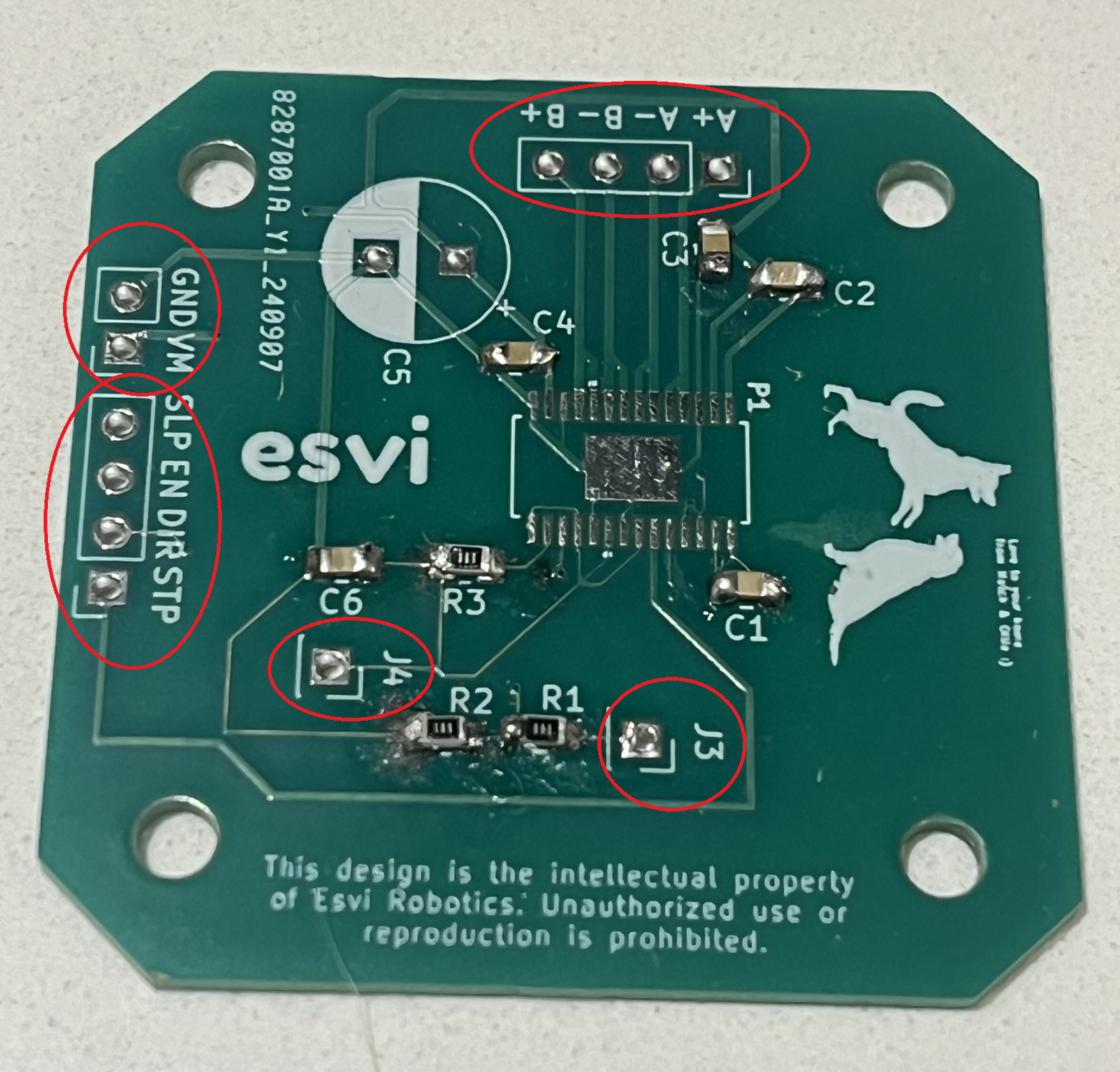
📌 Pro Tip: If a position doesn't work, you don't have to be married to it! You're allowed to move yourself or the board into different positions!
Warning: Don't forget to turn your soldering iron off when you're done using it! You are not Elmo!
╰┈➤ Go to Step 5: How to Solder
How to solder?
Do not solder alone, be safe and have a buddy. When using helping hands, only clamp to the corners. DO NOT clamp onto any traces, vias, pads, or you could risk damaging the board's function. 1. Using angle cutters or pliers, snap off the amount of pins you need. You can use your finger nail too. Be careful to not launch it into your eye... or your friend's.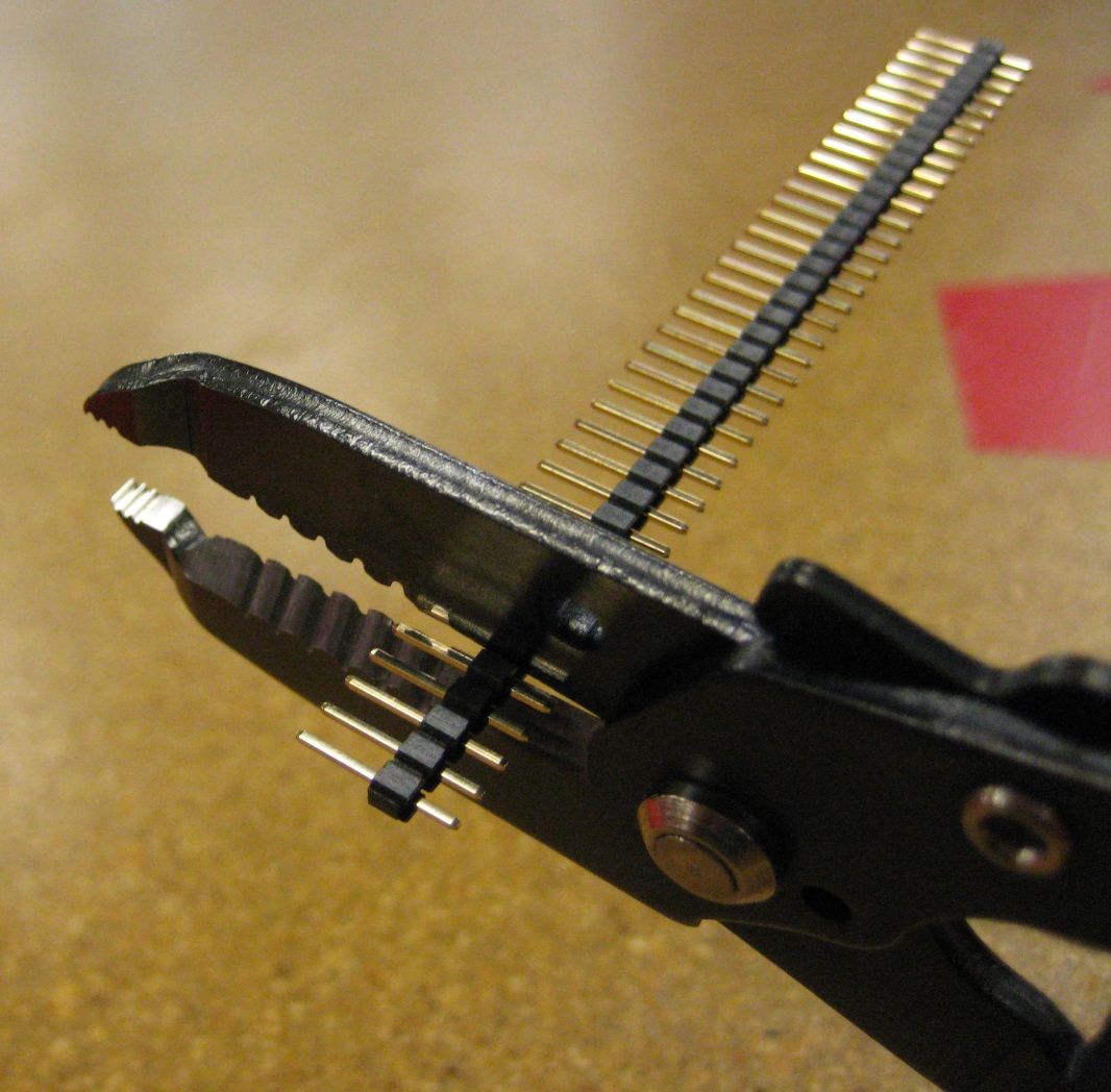 2. Apply some flux to the holes on the PCB.
3. If you have a breadboard, you can use it to hold the pins in place to solder (see video). If not, attach all of the pins, and flip the board upside down, bracing the low side with something. Short side goes in the holes.
Example:
2. Apply some flux to the holes on the PCB.
3. If you have a breadboard, you can use it to hold the pins in place to solder (see video). If not, attach all of the pins, and flip the board upside down, bracing the low side with something. Short side goes in the holes.
Example:
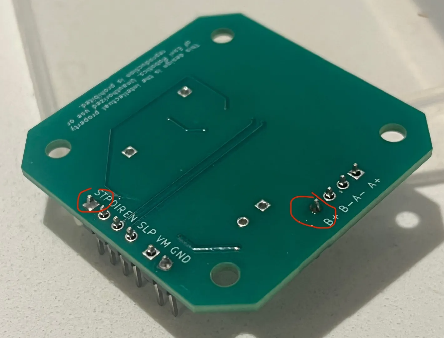
 4. Solder one pin of each of the sets first, let it cool and harden so the whole row stays put. Make sure the pins are not crooked at an angle! This is why you only solder one pin first, so you can remelt and adjust as needed.
 5. Go back and solder the rest of the pins.
📌 Pro Tip: You can use hydrogen peroxide to clean the boards of all the flux after.
Watch this video for a great explanation/demo of how to solder header pins using a soldering iron.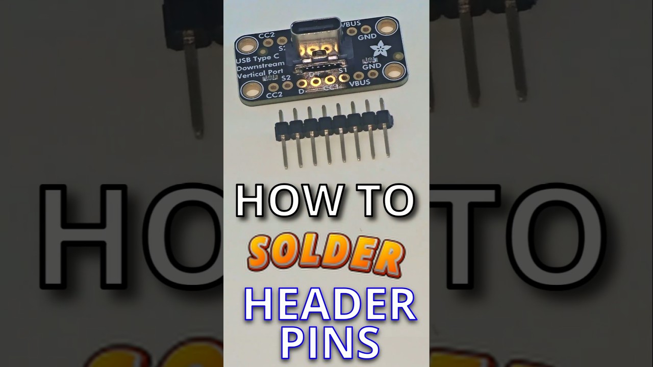
Click to watch a short example video.
╰┈➤ Go to Step 6: Quick Check
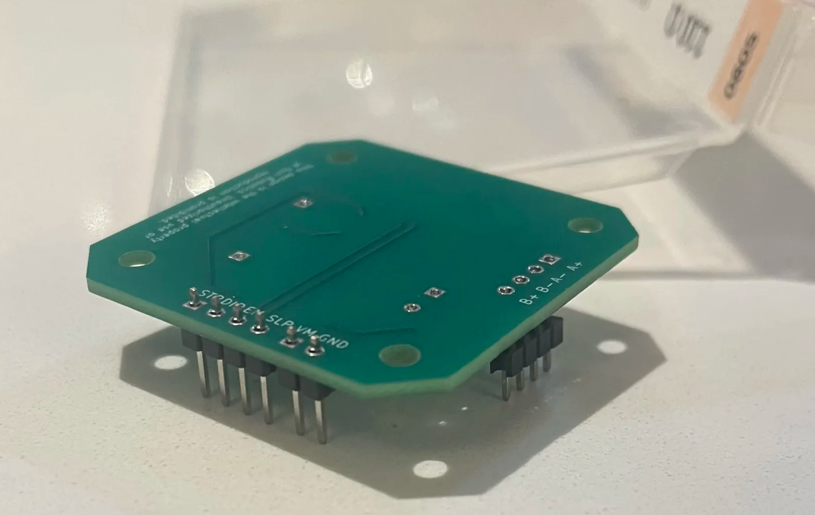
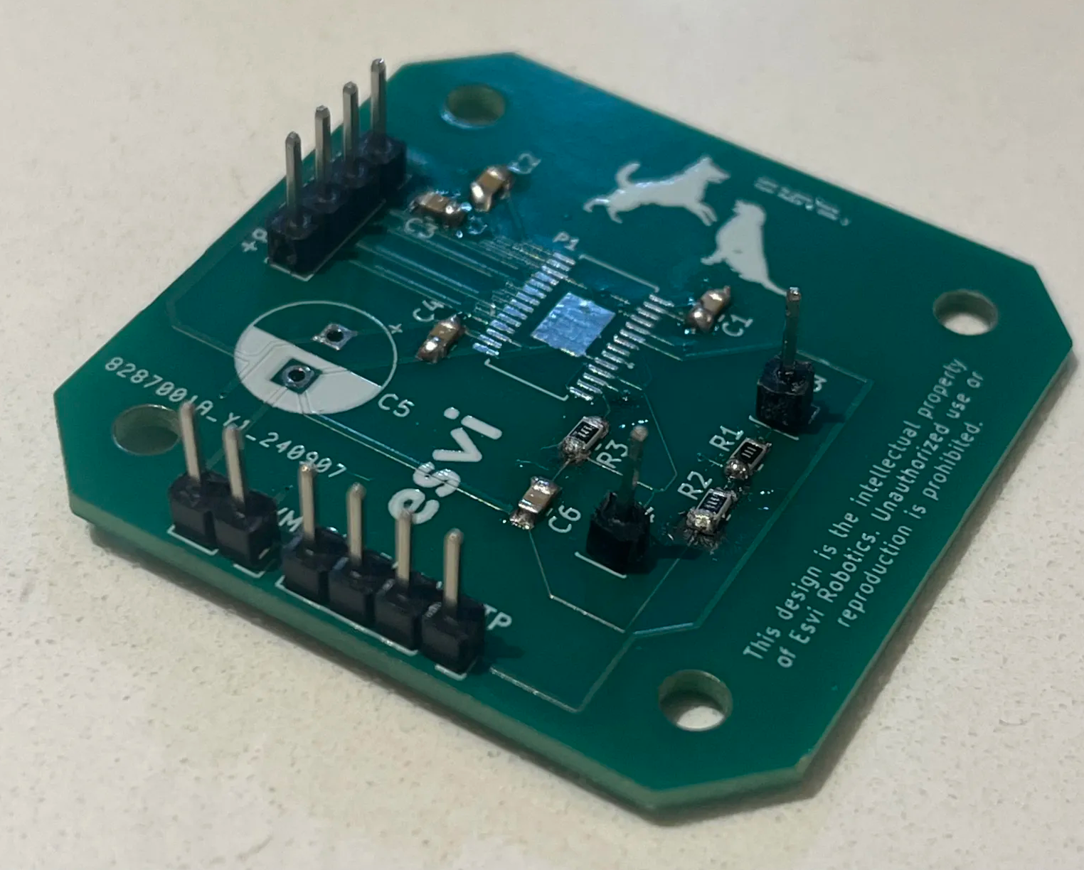
Quick Check!
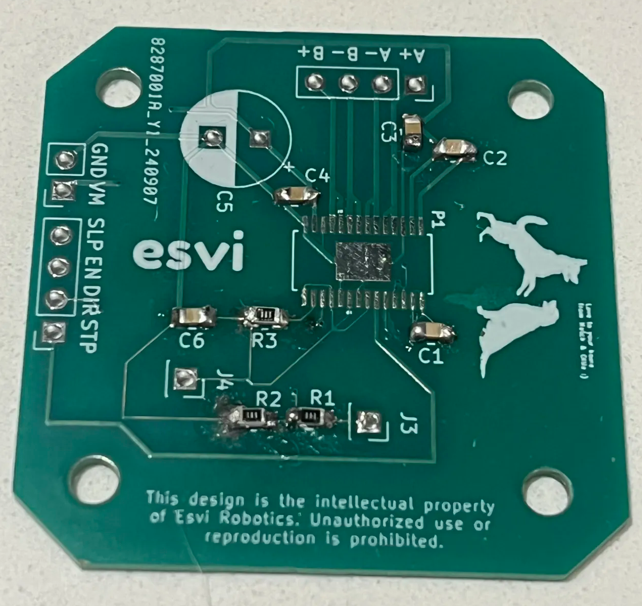
This is how it should look like after you're done.
What is the difference between a small SMD Capacitor vs the Big Cylinder Capacitor?
The size and shape of a capacitor depend on how much electricity it can store and how it’s built:- Big cylinder caps (like electrolytic capacitors) can store lots of charge and handle higher voltages. They’re often used for power supply smoothing.
- Small SMD caps store less charge and handle lower voltages, but they are tiny and fit on modern compact boards.
╰┈➤ Go to Step 2: Check Your Workspace
Check your workspace first.
When working with heated objects, first make sure your workspace is level and clean. Gather the practice PCB and the C5 cap you will be soldering.
Before You Start: Make sure you are working in a ventilated workspace. Working with soldering irons or heated tools is a burn hazard.╰┈➤ Go to Step 3: Soldering Iron Setup
Set up your soldering iron.
Set the temperature: Set soldering iron to ~650°F-800°F. The hotter you set your temp, the faster you will need to move because the solder will flow much easier, but you'll be at a higher risk of burning your components or board. However, too cold and you'll have trouble soldering. Try 700°F to start.
Preheat the iron: Allow the soldering iron to fully heat.
If you are not actively using your iron, put it down, or you might accidently burn yourself or something!╰┈➤ Go to Step 4: What to Solder
What to solder?
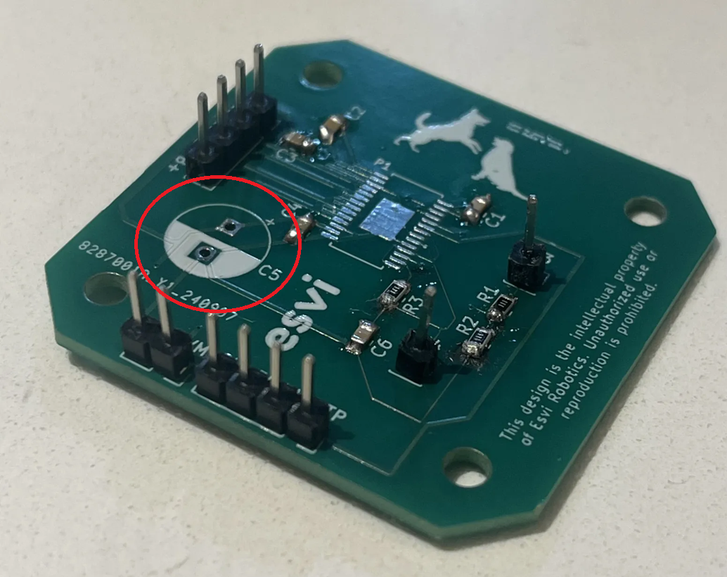
You will be soldering this cap.
Direction does matter!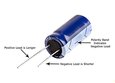 Check for the positive marking on the PCB and insert accordingly.
📌 Pro Tip: Do not touch the positive and negative leads together. If the capacitor has large enough capacitance, you'll get a nice fireworks show. The ones we give you are fine, just develop good practice habits now.
Warning: Don't forget to turn your soldering iron off when you're done using it! You are not Elmo!
╰┈➤ Go to Step 5: How to Solder
How to solder?
Do not solder alone, be safe and have a buddy. When using helping hands, only clamp to the corners. DO NOT clamp onto any traces, vias, pads, or you could risk damaging the board's function. 1. Find the positive side on the board, it's labeled. Insert the capacitor longer side in the positive hole til flushed with the board 2. With a finger holding the cap in place, flip the board and bend the leads down. This secures the cap in place so you can solder it. You can also tape it down (see video for reference).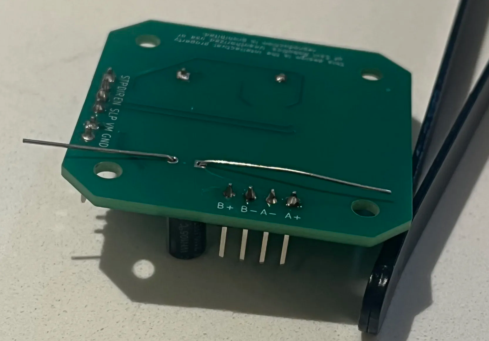 3. Apply some flux.
4. Touch the tip of the hot iron to the pad and the lead, then dab in some solder. Repeat for the other lead as well. Again, try not to touch the metal iron to both leads at the same time.
5. Cut the excess length off both leads with angle cutters.
3. Apply some flux.
4. Touch the tip of the hot iron to the pad and the lead, then dab in some solder. Repeat for the other lead as well. Again, try not to touch the metal iron to both leads at the same time.
5. Cut the excess length off both leads with angle cutters.
📌 Pro Tip: You can use hydrogen peroxide to clean the boards of all the flux after.
Watch this video for a great explanation/demo of how to solder an electrolytic capacitor using a soldering iron.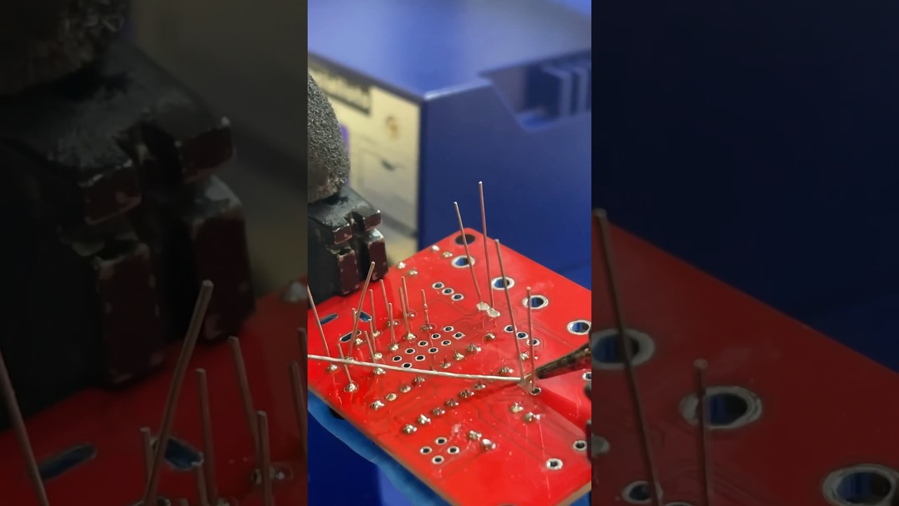
Click to watch a short example video.
╰┈➤ Go to Step 6: Quick Check
Quick Check!
This is how it should look like after you're done.